Table of Contents
Advertisement
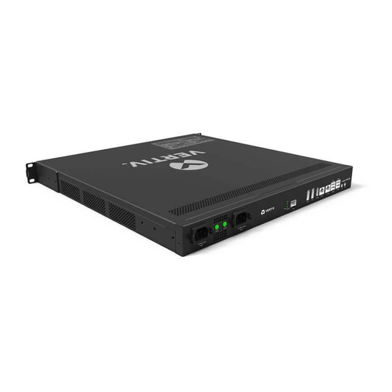
RDU501 Intelligent Monitoring Unit User Manual
Version V1.0
Revision date Jan 16, 2020
BOM
31013891
Vertiv provides customers with technical support. Users may contact the nearest Vertiv local
sales office or service center.
Copyright © 2019 by Vertiv Co.
All rights reserved. The contents in this document are subject to change without notice.
Vertiv Co.
Address: 151 Lorong Chuan, Lobby D New Tech Park, #05-04 New Tech Park Singapore,
556741 Singapore
Homepage: www.vertiv.com
Advertisement
Table of Contents

Related Manuals for Vertiv RDU501


Summary of Contents for Vertiv RDU501
- Page 1 Version V1.0 Revision date Jan 16, 2020 31013891 Vertiv provides customers with technical support. Users may contact the nearest Vertiv local sales office or service center. Copyright © 2019 by Vertiv Co. All rights reserved. The contents in this document are subject to change without notice.
- Page 2 Reproduction, disclosure, or use without specific authorization from Vertiv Group Corporation is strictly prohibited. Vertiv and the Vertiv logo are trademarks or registered trademarks of Vertiv Group Corporation. Trellis™ is a trademark of Vertiv, Inc. All other trademarks are the property of their respective owners.
-
Page 3: Table Of Contents
2.3.1 Install expansion card ..........................12 2.3.2 Install intelligent sensors .......................... 12 2.3.3 Install physics sensor ..........................13 Chapter 3 Web Interface of RDU501 ..........................15 3.1 Login Preparation ..............................15 3.1.1 Checking IP Address Connectivity ......................15 3.1.2 Checking browser version ........................15 3.2 Login RDU501 .............................. - Page 4 3.4 Menu Items ................................. 21 3.4.1 Device ..............................21 3.4.2 Security Management ..........................24 3.4.3 IT Management ............................32 3.4.4 Thermal management..........................42 3.4.5 Power Management ..........................48 3.4.6 Data Management ........................... 50 3.4.7 Smart Solution Modeling .......................... 63 3.4.8 Configuration Management ........................71 3.4.9 System setting ............................
-
Page 7: Chapter 1 Product Introduction
Chapter 1 Product Introduction Chapter 1 Product Introduction RDU501 intelligent monitoring unit (referred to as “RDU501”) features the Web access, digital input/output, analog input/output, sensor, UPS, air conditioner and PDU, and provide USB, DP, HDMI and other interfaces to meet TCP/ IP, optical fiber, and RS232/485 networking requirements. - Page 8 Chapter 1 Product Introduction Input power There are two isolated power inputs on the rear panel of the RDU501 main unit. The location is shown in Figure 1-1. The power input parameters are shown in Table 1-1. Table 1-1 Power input parameters...
- Page 9 Serial port The RDU501 main unit provides four independent serial ports: serial port 1, serial port 2, serial port 3, and serial port 4. The location is shown in Figure 1-1. The interface adopts RS-485/232C (self adaptive) communication mode, and the communication parameters are shown in Table 1-9.
-
Page 10: Expansion Card
Chapter 1 Product Introduction 1.1.2 Expansion card The four expansion slots of the RDU501 main unit support hot-swap connection of EXP8COM card, EXP8DIAI card, EXP8DOAO card and EXP2DI6DO card. EXP8COM card (optional) The EXP8COM card provides 8 serial ports and supports RS232/RS485 communication to connect user device (RS232/RS485 line-sequence adaptive). - Page 11 4. The DI and DO line sequence of the EXP2DI6DO card refers to the line sequence of DI/Smoke and DO; 5. The close and open of the DO sampling signal in the RDU501 software uses the normally open contact 6 (normally open)
-
Page 12: Main Functions
Chapter 1 Product Introduction 1.2 Main Functions The main functions of RDU501 are given in Table 1-15. Table 1-15 RDU501 main functions Main functions Descriptions Device Realize video surveillance of the computer room environment, and the data acquisition and processing of... -
Page 13: Technical Specifications
Extend RDU501 function and access capability through authorization code management Title bar settings Set the title above the web page Display product serial number, feature code and version information of RDU501, and About RDU501 provide download of user manual 1.3 Technical Specifications 1.3.1 Environmental Specifications... -
Page 14: Performance Specifications
EXP8DOAO depth 210mm <±1 mm EXP2DI6DO weight <0.5kg 1.3.3 Performance Specifications The performance specifications of the RDU501 are shown in Table 1-18. Table 1-18 Performance specifications Max number of Connecting length Device type Connected devices Cable standard connections / connected... -
Page 15: Product Certification
COM is no more than six; : The RDU501 supports up to 32 console devices. There is no more than one console device cascaded with single COM. Note: [10] COM connected to the console device cannot connect to other intelligent devices at the same time;... -
Page 16: Chapter 2 Hardware Installation
2.1.3 Space requirements Place the RDU501 away from heat sources It is recommended to install the RDU501 in a 19-inch standard cabinet. Leave at least 10 mm of space around the device to ensure sufficient space for heat dissipation. 2.1.4 Installation Tools The installation tools are shown in Table 2-1. -
Page 17: Install Rdu501 Main Unit
4.Mounting ears (2pcs) Figure 2-2 Install the guide rails and mounting ears in the rear side 3. Use the M6 floating nut and M6 screw to fix the RDU501 main unit to the rack through the mounting ears on both sides. -
Page 18: Install Accessories Of Expansion Card And Sensor
Remove the baffles of the expansion slots (Slot1, Slot2, Slot3, or Slot4) on the front panel of the RDU501. Insert the expansion card into the expansion slot of the RDU501 and tighten the screws on both sides, as shown in Figure 2-4. -
Page 19: Install Physics Sensor
There are two methods to connect the smoke detector, flood sensors, infrared sensors, and door magnetic switches: Directly connect the DI port on the front panel of the RDU501 (Silk Screen Printing is DI1, DI2, Smoke1, and Smoke2, each port can be arbitrarily connected to one of smoke detector, flood sensors, infrared sensors, and door magnetic switches). - Page 20 Chapter 2 Hardware Installation Connect the RDU501 through the IRM-S04DI or IRM-S04DIF: Connect the sensor to the IRM-S04DI or IRM-S04DIF Digital input port. For the wiring sequence, refer to the IRM-S04DI Phoenix Port Intelligent Digital Input Sensor User Manual or IRM- S04DIF RJ45 Port Intelligent Digital Input Sensor User Manual.
-
Page 21: Chapter 3 Web Interface Of Rdu501
3.2.1 Authorized Startup 1. When logging in to the RDU501 for the first time, open the browser and enter the IP address of the RDU501 in the address bar (the default IP of LAN1 is 192.168.0.254; the default IP of LAN2 is 192.168.1.254). Open the authorized startup page, as shown in Figure 3-1. -
Page 22: Login Page
3.2.2 Login page 1. Open the browser and enter the IP address of the RDU501 in the address bar. The login page appears, as shown in Figure 3-2. If the login page does not appear, see “Question 5” in section 4.2 Troubleshooting. -
Page 23: Rdu501 Main Page
2. The retrieved password is a new password generated randomly by the system. Please modify it after you log in successfully. 3.3 RDU501 Main Page In the RDU501 homepage, click on the left Homepage menu to see two submenus, including: Power and Environment Overview and IT Device Overview. - Page 24 Chapter 3 Web Interface of RDU501 Press the left mouse button to drag the hotspot to move the hotspot location. Click the hot spot , the Edit and Delete options will pop up, as shown in Figure 3-5. Figure 3-5 Setting page Click Edit to bring up the device signal setting page.
- Page 25 Chapter 3 Web Interface of RDU501 Note After modifying the hotspot information, you need to click the Save button to save, otherwise the hotspot configuration information will be lost. 3. Background setting Click the Change Background Image button , the page shown in Figure 3-7 is displayed.
-
Page 26: Overview Of It Device
6. The last 10 events of the console device IPMI Figure 3-9 RDU501 homepage (IT device overview) 1. U space availability is the ratio of the number of available U spaces to the total number of U spaces. 2. The IPMI device online rate is the ratio of the number of online IPMI devices to the total number of IPMI devices. -
Page 27: Time Calibrating Link
6. Display the last 10 events of the console device. 3.3.3 Time calibrating link The RDU501 system time is displayed at the top right of the page. Clicking on the system time will jump to the time calibration page. For details, see Time Calibration in section 3.4.9 System setting. - Page 28 1. The ENV-TH device in the Device is a virtual device, indicating all temperature and temperature and humidity sensors connected to the RDU501 body and the name cannot be changed. 2. The attention signal can be set on the Device - Acquisition Signal page.
- Page 29 Chapter 3 Web Interface of RDU501 1. List of available controls 2. Configure controls 3. Delete controls 4. Back to browse 5. The same type of device is valid 6. Restore the default 7. Save the configuration Figure 3-13 Device Overview -Edit In the edit state, click the icon to batch configure other devices of the same type;...
-
Page 30: Security Management
Security Management monitors and manages the security of the cabinet through video surveillance, access control, and fire fighting management functions. In the RDU501 homepage, click on the Security Management menu to see three submenus, including: Access Control, Fire Fighting Management, and Video Management. - Page 31 1. The user can set the display or hide access control management module in System Settings -> Monitoring Unit -> Settings Signal, as shown in Figure 3-19. 2. After the RDU501 is connected to the higher level management platform, the access management function can be implemented through the higher level management platform.
- Page 32 Chapter 3 Web Interface of RDU501 Figure 3-19 Show or hide the access control module 2. Authority management Click the Authority Management tab under the Access Control Management menu to display the page shown in Figure 3-20. Figure 3-20 Authority management After the user selects the Access Control Device and the Door Lock, check or uncheck the access control card and click the Save button to authorize or deauthorize the access control card.
- Page 33 Chapter 3 Web Interface of RDU501 Figure 3-21 Historical query The user can select the access control device and click the Query button to query the history of the event. Click the Download button to download. Clicking on the invalid card swiping event in the history log to add this card, you can jump to the access control card management tab to add the card.
- Page 34 Chapter 3 Web Interface of RDU501 Figure 3-24 Video device management 1. Video device management Enter the IP address of the video device, Login user name and Password, HTTP port, HTTPS port, RTSP port, and click the Test connection button to test whether the video device is successfully connected. If the prompt message "Video device connection test is successful!"...
- Page 35 Chapter 3 Web Interface of RDU501 Figure 3-26 Security setting 2 2. Live video Click the Live Video tab under the Video Management menu to display the page shown in Figure 3-27. Figure 3-27 Live Video Table 3-1 Live video page icon description...
- Page 36 Chapter 3 Web Interface of RDU501 3. Video playback Click the Video Playback tab under the Video Management menu to display the page shown in Figure 3-28. Figure 3-28 Video playback Table 3-2 Video playback page icon description Icon Descriptions...
- Page 37 Chapter 3 Web Interface of RDU501 Figure 3-29 Parameter settings The parameter setting tab provides settings for various parameters of the camera. For details of the parameters, please refer to the Network Camera Operation Manual provided with the NVR. Among them, the channel management is only for the NVR setting, and the IPC camera does not involve this function.
-
Page 38: Management
IT management monitors and manages IT equipment through IPMI device management, console device management, and server shutdown management. In the RDU501 homepage, click on the IT Management menu to see seven submenus, including: IPMI Device List, IPMI Device Management, IPMI Device Alarms, Console Device List, Console Device Management, Console Log Data, and Server Shutdown Management. - Page 39 Chapter 3 Web Interface of RDU501 Figure 3-33 IPMI device overview Click the Time Setting tab in the device detailed information page to enter the time setting page. After selecting the time to be set, click the Save button to complete the modification of the BMC time of the device. As shown in Figure 3-34.
- Page 40 Chapter 3 Web Interface of RDU501 Figure 3-36 Event Log Click the FRU Information tab on the device detailed information page to enter the FRU information page, which displays the FRU System Board's properties and values. As shown in Figure 3-37.
- Page 41 Chapter 3 Web Interface of RDU501 Figure 3-38 Sensor information 2. IPMI device management Click the IPMI Device Management submenu under the IT Management menu. You can modify or delete the information of an IPMI device, as shown in Figure 3-39.
- Page 42 Chapter 3 Web Interface of RDU501 After modifying the device information, you need to click the Save Configuration button to make the configuration take effect. After clicking Save Configuration, the User Security Verification dialog box pops up, prompting you to enter the current user's login password.
- Page 43 When a user accesses the device through RDU501, the device is defined as idle and the card is displayed in green. When the device is being accessed by the user through RDU501, the device is defined as being in use and the card is displayed in red.
- Page 44 OK button, as shown in Figure 3-49. When you add a keyword to a specific device, you can directly select the keywords that have been added in the default keyword. The RDU501 can filter the input/output information of the serial port target device through user-defined keywords and generate an event when the keyword matches.
- Page 45 Chapter 3 Web Interface of RDU501 Figure 3-49 Add default keywords Click the Add button to open the page for adding devices. After entering the device information, click the Save button, as shown in Figure 3-50. Figure 3-50 Add a console device After modifying the device information, you need to click the Save Configuration button to make the configuration take effect.
- Page 46 Note In the RDU501 standard product, this module only provides relatively basic functions. If you have more functional requirements, please contact us. Click the Server Shutdown Management submenu under the IT Management menu to open the Server Shutdown Management page and display the strategy list, as shown in Figure 3-53.
- Page 47 Chapter 3 Web Interface of RDU501 Figure 3-53 Server shutdown management Enable strategy The icon in the strategy list indicates that the current strategy is disabled. Clicking on the icon will bring up the prompt "Are you sure to enable the strategy?", click the OK button to enable the strategy.
-
Page 48: Thermal Management
Chapter 3 Web Interface of RDU501 Figure 3-55 Add input conditions After filling in the basic information and input conditions of the conditional strategy, click the Save button in the lower right corner of the page. After saving successfully, it will automatically return to the strategy list page. - Page 49 In the RDU501 homepage, click on the air-conditioning teamwork control menu on the left side, you can see two sub- menus, including: running status and teamwork control settings.
- Page 50 Chapter 3 Web Interface of RDU501 The description of the RDU501 teamwork control function is as follows: The standard version only supports 1 air conditioning group. The default is [1] TMW. The addition and deletion teamwork functions are not provided and the group name cannot be changed. The authorized version is not subject to this restriction.
- Page 51 Chapter 3 Web Interface of RDU501 Figure 3-61 Teamwork control parameter setting page (added) The parameter description of the group parameter setting page is shown in the table below. Add, modify or delete the air conditioner in the group on the air conditioner parameter setting page, please refer to 2) air conditioner parameter setting in this section;...
- Page 52 1. If you need an authorized version of RDU501, please contact Vertiv Customer Service Center for purchase. 2. The standard version only supports 4 air conditioners by default, including Vertiv DME series air conditioner and SmartRow V2 built-in air conditioner.
- Page 53 Chapter 3 Web Interface of RDU501 Figure 3-63 Add / modify air conditioner page (DI connection) Procedures for adding air conditioner: 1) In the Air conditioner index bar, enter the index of the air conditioner in the group (the default index will be increased from 1);...
-
Page 54: Power Management
In the RDU501 home page, click on the Power Management menu on the left to see three submenus, including: real-time energy consumption, history, and energy consumption settings. - Page 55 Figure 3-65 Power management history record Note 1. The RDU501 records and displays up to 1000 energy consumption history records. 2. After the user has set the energy consumption, the system will save the record every 24 hours according to the user's configuration.
-
Page 56: Data Management
The Data Management function provides users with various types of historical data and log data query services. In the RDU501 home page, click the Data Management menu on the left to display 7 submenus, including: active alarm, historical alarm, device data, historical data, Smart report, log data, and clear data. - Page 57 Chapter 3 Web Interface of RDU501 Figure 3-67 Active alarm 1. The Active alarm can display the current alarm of the system by clicking the alarm level on the tab of the Active alarm page. 2. Click the Alarm confirmation button to confirm the alarm. The confirmed alarm will no longer participate in the alarm linkage, and the alarm notification will be sent only once.
- Page 58 Chapter 3 Web Interface of RDU501 Figure 3-69 Historical alarm query 1. Historical alarm query Click the Historical alarm query submenu to view historical alarm records. Select a device (such as "All Devices") and set the start time (for example "2019-01-01 00:00:00") and the end time (for example "2019-01-02 23:59:59").
- Page 59 Chapter 3 Web Interface of RDU501 Click the Alarm statistics report submenu to view alarm statistics. Select the report type (for example, "Statistic by device alarm level"), set the query period (for example, "2019-01-01 00:00:00" and "2019-01-01 23:59:59"), and then select the device type.
- Page 60 Chapter 3 Web Interface of RDU501 Figure 3-72 Statistics by site Device data Click the Device Data submenu under the Data Management menu to pop up the page shown in Figure 3-73, which contains four sub-pages: Device Information List, SNMP MIB Export, Asset Information, and Asset Batch Configuration.
- Page 61 Click the Device Data submenu under the Data Management menu, and then click the Asset Information tab to bring up the page shown in Figure 3-75. You can view all asset information under the current RDU501, select the query type, and enter the query conditions to view all eligible asset information.
- Page 62 Chapter 3 Web Interface of RDU501 Figure 3-75 Asset information 1) Asset information inquiry The asset information provides 4 ways to query: Query by name: Enter a non-null string to return the asset information containing the string in the asset name;...
- Page 63 Chapter 3 Web Interface of RDU501 Figure 3-78 Query by ID range Query by warranty date: Select a date and return the asset information with warranty period within 3 months before and after the date. Figure 3-79 Query by warranty date The queried asset information is displayed in a tabular form, as shown in Figure 3-80.
- Page 64 1. When the RDU501 is started for the first time, there is no asset data on the asset information page. You need to manually add common assets by adding the device asset or asset information page through the Save Configuration button on the Configuration Management ->...
- Page 65 1. If the asset code in the file is different from the existing asset code in RDU501, a new common asset is added. 2. If the asset code in the file is the same as the existing asset code in RDU501, the current information of RDU501 is overwritten with the asset information in the file.
- Page 66 Chapter 3 Web Interface of RDU501 Figure 3-85 Data report Note The page displays up to 500 query results. If there are more than 500 PCS, you need to download using “Download” to download all query results. 2. Curve report As shown in Figure 3-86, select a report name (for example, "TH Temperature Cure") and set the query period (for...
- Page 67 Chapter 3 Web Interface of RDU501 Note Report Name: For the name of the report added on the Curve Report Settings page, please refer to the next section. 3. Curve report settings As shown in Figure 3-87, all the curve report configurations that have been added are displayed. Click the delete button on the right to delete the corresponding report configuration.
- Page 68 Chapter 3 Web Interface of RDU501 1. Smart Report View In the page shown in Figure 3-90, select a report name (for example, "Cold Aisle Temperature Curve Report") and set the query period (for example, from 2019-01-01 00:00:00 to 2019-01-01 23:59:59), and then click the Query button.
-
Page 69: Smart Solution Modeling
Similarly, the user can clear any other available data in the drop down box. 3.4.7 Smart Solution Modeling In the RDU501 home page, click on the Smart Solution modeling menu on the left to see five sub-menus, including: Thermal Management, Power Management, Asset Management, 2D Modeling, and Assets on Shelf. - Page 70 Chapter 3 Web Interface of RDU501 Thermal Management Click the Thermal Management submenu under the Smart Solution Modeling menu to open the page shown in Figure 3-94. Figure 3-94 Thermal Management The thermal management page displays the temperature field data of each rack in the module in 2D. Wherein FT represents the front door temperature and RT represents the rear door temperature.
- Page 71 Chapter 3 Web Interface of RDU501 Note 1. If 2D modeling is not completed, when accessing the thermal management page, prompt “Please configure 2D modeling”. Click on "Please configure 2D modeling" and you will be taken to the 2D modeling page.
- Page 72 Chapter 3 Web Interface of RDU501 Figure 3-97 Asset Management The asset management page displays the space capacity usage of each rack in the module in 2D mode. The space capacity of the rack = the U-number occupied by the assets on shelf/ the total U-digit number of the rack.
- Page 73 Chapter 3 Web Interface of RDU501 1. Add SmartRow 2. Add SmartAisle 3. Temperature field color setting 4. Capacity color setting 5. Save 6. Clear Figure 3-99 2D modeling 1. Add/modify/delete model Click the Add Model icon (including SmartRow and SmartAisle) on the 2D Modeling page to create a model of the corresponding type on the right side.
- Page 74 Chapter 3 Web Interface of RDU501 Figure 3-101 SmartAisle rack properties After adding or modifying module properties and rack properties, you need to save by clicking the Save icon at the top right of the page. When deleting the model, click the Clear icon at the top right of the page, a prompt box will pop up, prompting the modeling information to be deleted, and clear the relevant asset binding information.
- Page 75 Chapter 3 Web Interface of RDU501 Figure 3-102 Temperature field color setting The level range of the temperature field of the module and the temperature field of the IT equipment can be set in the temperature field color setting page. Drag in the level range, change the level range and click Save to complete the setting.
- Page 76 Chapter 3 Web Interface of RDU501 Click the Assets on Shelf menu under the Smart Solution Modeling menu to open the Assets on Shelf page. The Assets on Shelf page displays the space capacity of each rack in the module in 2D by default.
-
Page 77: Configuration Management
-> 2D Modeling -> Capacity Color Setting. 3.4.8 Configuration Management In the RDU501 homepage, click the Configuration Management menu on the left to view six submenus, including: Infrastructure Device Mgmt, Batch Configuration, Device Signal Configuration, Notification Mode Configuration, Email SMS Configuration, and Alarm Linkage. - Page 78 Chapter 3 Web Interface of RDU501 Figure 3-107 Device management In the page shown in Figure 3-107, users can add/modify/delete device information as follows: Add equipment Click the Add button, the interface shown in Figure 3-108 will pop up, and the corresponding device will be added.
- Page 79 OK button. After the password verification is passed, the system will jump to the system restart interface, as shown in Figure 3-110. Figure 3-110 System restart page 8) Re-login to the RDU501 system and the newly added device will be displayed in the list on the device management page. Note ...
- Page 80 Chapter 3 Web Interface of RDU501 3) Click the Modify button to modify the device information; 4) Click the Save Configuration button to make the device-modification take effect, the same as adding a new device. Note 1. The “Save Configuration” button can be clicked to save all operation results at once.
- Page 81 Chapter 3 Web Interface of RDU501 Figure 3-112 Batch configuration Users can perform Upload and Download operations to complete system batch configuration. Note 1. Only the admin user has the authority to perform batch configuration. If batch configuration cannot be performed, click View Help for help.
- Page 82 Chapter 3 Web Interface of RDU501 2. Modify signal Click Modify Signal to pop up the page shown in Figure 3-114. Figure 3-114 Modify signal In the page shown in Figure 3-114, the user can modify the signal name, the storage period of the acquisition signal, the storage threshold of the acquisition signal, the signal unit of the set signal, and the alarm level of the alarm signal according to the device type or device name.
- Page 83 Chapter 3 Web Interface of RDU501 Figure 3-116 Modify the storage cycle/storage threshold Click on the table title of “New Storage Cycle”, the storage cycle input box will pop up, enter a new storage cycle (for example: 3600), click the OK button, and all non-zero storage cycles in the device type acquisition signal will be updated to 3600.
- Page 84 Chapter 3 Web Interface of RDU501 Figure 3-118 Modify the signal unit 5) Restore the default name Select the Device name check box, select any device in the drop-down box, and then select a signal type in the signal type drop-down box, the signal list shown in Figure 3-119 appears, you can click the Restore default name button on the right side of the device.
- Page 85 Chapter 3 Web Interface of RDU501 Figure 3-119 Restore the default name Note 1. For ENV-TH, ENV-THD and ENV-4DI, the system has the function of linkage modification of the signal name, that is, if the name of the acquisition signal is modified, and the corresponding control signal, setting signal and alarm signal name will be modified accordingly, so the page only provides the function to modify the acquisition signal name.
- Page 86 Chapter 3 Web Interface of RDU501 Figure 3-121 Modify signal status 2 Notification mode configuration 1. Power and environment device alarm notification settings Click the Notification Mode Configuration submenu under the Configuration Management menu, and then click the Power and Environment Device Alarm Notification Settings tab. The page shown in Figure 3-122 is displayed.
- Page 87 Chapter 3 Web Interface of RDU501 Note 1. The user must first select the notification mode before the Alarm Notification Configuration Table at the bottom of the page can be edited; 2. When you select a device name, all devices are configured with the same alarm level.
- Page 88 Chapter 3 Web Interface of RDU501 Figure 3-124 Console device event notification settings Note 1. The user must first select the Notification mode, and the Alarm notification configuration table at the bottom of the page can be edited; 2. When the device name is selected, all devices are configured with alarm notifications at the same time.
- Page 89 Chapter 3 Web Interface of RDU501 Figure 3-125 System status timed notification configuration Note 1. The system Status Timed Notification Configuration must be used in conjunction with the Power and Environment Device Alarm Notification Setting. Otherwise, the User Name, Notification Mode, and Notification Language cannot be selected.
- Page 90 SMS module configuration 1) Connect the SMS MODEM through the USB port (USB1~USB4 port on RDU501 panel) according to the need (only 1 SMS MODEM can be connected), and then select the Port type; 2) Select the type of SMS module (GSM/CDMA) according to the model of the incoming SMS MODEM;...
- Page 91 Chapter 3 Web Interface of RDU501 3) Set the communication parameters of the short message MODEM; 4) Click the Save button to save the current user's SMS module configuration. RDU multimedia voice notification system settings 1) Enter the server IP address at the Server IP address;...
- Page 92 Chapter 3 Web Interface of RDU501 Note 1. The SMS balance information is forwarded to the admin user's mobile phone. The admin user is required to configure the mobile phone number. 2. Since there is a certain delay in the balance message sent by the carrier, please check the receiving time of the SMS to judge whether the queried SMS information has been updated.
- Page 93 Chapter 3 Web Interface of RDU501 Figure 3-129 Alarm linkage configuration 2 First, select an operator, for example, "OR", the expression is "Signal 1 [Input 1 Register] or Signal 2 [Input 2 Register] = Output Signal [Output Register, Video Device]".
- Page 94 If the temperature and humidity sensor 01 of the RDU501 system needs to be connected to the temperature and humidity sensor of the RDU501 system, the alarm indicator will be illuminated. If the alarm indicator is installed on the DO1 interface, you can complete the alarm linkage function through the following configurations.
-
Page 95: System Setting
Figure 3-132 shows the configuration method. The meaning is that when the alarm signal RDU501 DI1 is turned on or the RDU501 DI2 is turned on to generate an alarm, the RDU501 DO1 is triggered to be closed, thereby lighting the alarm indicator. - Page 96 Chapter 3 Web Interface of RDU501 Figure 3-134 Monitoring unit (setting signal) Note If the Current alarm block is set to "Yes" in the Setting Signal tab, the current alarm will be blocked. In this case: 1. Except for the current alarm that is blocked, all others are terminated.
- Page 97 1. If the NIC chooses to use a static IP address, the DNS address cannot be obtained automatically. 2. After modifying the IP address, the user needs to log in to the RDU501 again with the new network address. By default, will redirect to the IP address of the network card 1.
- Page 98 Click the Network Settings submenu under the System Settings menu, then click the SNMP Settings tab to configure the SNMP agent. The SNMP agent of the RDU501 system supports both V2 and V3 versions: As shown in Figure 3-137, the SNMP V2 can be set as follows: 1) Set the NMS IP (host IP address of the SNMP agent data receiving end);...
- Page 99 Figure 3-138 SNMP (V3) setting Note RDU501 does not provide SNMP proxy service by default. If SNMP service authorization is required, please contact Vertiv Customer Service Center for purchase. 4. Security settings Only administrators can browse and configure Security settings.
- Page 100 Chapter 3 Web Interface of RDU501 Figure 3-139 Security settings The security settings include the Web Access Port Settings and the Web Access Security Strategy. 1. Web access port settings: The protocol that can be used to access the web page is HTTP or HTTPS. The default is the HTTP protocol.
- Page 101 Chapter 3 Web Interface of RDU501 Note The mobile terminal APP is allowed to connect to the RDU 501 only when the web access method adopts HTTPS. 2. Web Access Security Strategy: Select whether to enable the web access security strategy. The default is enabled.
- Page 102 Chapter 3 Web Interface of RDU501 Figure 3-143 User Management Refresh expiration date If the web access security strategy is enabled, the account expiration time for the selected user is displayed on the interface. The administrator clicks the refresh expiration icon to refresh the new password expiration date for the selected user.
- Page 103 3. If the binding sequence number is not entered, the system will bind the serial number of the first two mobile devices logged in from the APP. 4. After binding, the system only allows the bound mobile terminal to access the RDU501 from the APP. If you want to re-bind, just modify or delete the binding serial number.
- Page 104 Figure 3-146 Time calibration The RDU501 can also acquire the local time, select the current calibration time and click the Get Local Time button to get the local time, then click the Setting button to make the new time take effect.
- Page 105 If the user uses the recovery function, the RDU501 will restore the original configuration scheme. After the recovery operation, please confirm to wait for 1 minute and then re-enter the RDU501 through the network to make it complete initialization. Site information settings Click the Site Information Settings submenu under the System Settings menu to bring up the page shown in Figure 3-148.
- Page 106 System Title text box and click the CONFIRM button to make it effective. About RDU501 In the RDU501 homepage, click the About RDU501 submenu under the System Settings menu. The page shown in Figure 3-151 is displayed. The RDU501 page displays the software version, serial number, and feature code of the RDU501 and provides the user manual download link.
-
Page 107: Chapter 4 Maintenance
The RDU501 has two network cards. Please confirm whether the Ethernet cable is plugged into the wrong interface. If it is a static IP address, refer to the Ethernet port in the RDU501 main unit section for the default IP value of the RDU501. - Page 108 Step 1: Connect a monitor through the DP1 port or HDMI port on the RDU501 host, and then insert a keyboard through the USB port on the RDU501 host. Step 2: Press Ctrl + Alt + F1 at the same time to switch to the command line interface of RDU501, as shown in Figure 4-4.
- Page 109 Answer: Take following steps below to troubleshoot: 1) Confirm whether the intelligent sensor is connected to the SENSOR port of the RDU501. At the same time, the address “1” within the group can only be connected to SENSOR1, and the address “2” within the group can only be connected to SENSOR2.
- Page 110 If it is correct, go to step 4; 4) If the above check results are normal, it may be that the server side rejects the session request of the RDU501. Please contact Vertiv technical service personnel.
-
Page 111: Appendix 1 Abbreviations
Appendix 1 Abbreviations Appendix 1 Abbreviations Alternating Current Digital Input Internet Explorer, a Web browser developed by Microsoft@ Frequently Asked Questions IPMI Intelligent Platform Management Interface Baseboard Management Controller Field Replaceable Unit Power Usage Effectiveness RDU501 Intelligent Monitoring Unit User Manual... -
Page 112: Appendix 2 Standard Configuration List
Appendix 2 Standard Configuration List Description Quantity Unit RDU501 intelligent monitoring unit RDU501 intelligent monitoring unit installation and commissioning manual Small hardware - 21-inch mounting ears Small hardware--RDU line card Wire and Cable-IEC60320 C13 Plug-IEC60320 C14 Plug-H05VV-F-3C-1mm^2-Black-2000mm-EU Small hardware -mounting ears... -
Page 113: Appendix 3 Fcc Certification Description
Vertiv Tech Co., Ltd. Address: 1050 Dearborn Drive, Columbus, OH 43085, USA Homepage: www.vertiv.com Customer service hotline: 614-888-0246 RDU501 Intelligent Monitoring Unit User Manual...
Need help?
Do you have a question about the RDU501 and is the answer not in the manual?
Questions and answers