Advertisement
Quick Links
Advertisement

Related Manuals for Foif J2-2

Summary of Contents for Foif J2-2
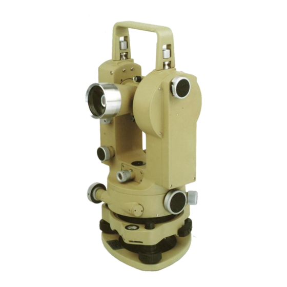
- Page 1 INSTRUCTION MANUAL J2-2 Optical Theodolite Suzhou FOIF Co., Ltd.
- Page 2 Dear Customer: Congratulations! We, FOIF are proud to present you with a J2-2 optical theodolite. Your theodolite is a rugged and reliable instrument whose performance and design are not surpassed. To fully appreciate and protect your investment, we suggest that you take the necessary time to read and fully understand this manual.
- Page 3 The model and the serial number of your product are indicated on the type plate. Enter the model and the serial number in your manual and always refer to this information when you need to contact your agency or FOIF authorized service workshop.
-
Page 4: Table Of Contents
Contents Applications Technical Data Construction Method of operation Testing and Adjusting Care of Instruments Optional Accessories Document... -
Page 5: Applications
Applications: J2-2 optical theodolite is a kind of precision angle-measuring instrument. It plays a very important orle in geodesic survey and engineering measurement, therefore it is widely used in third-order, fourth-order trainglulation, building, roadwork, pipe playing, trnnelling, mining, cadastral survey as well as machine tooling and installation etc. - Page 6 Field of view at 1000m Shortest focusing distance Multiplication factor Additive constant Grass Circles 360° Graduation diameter: HZ circle 90mm V circle 70mm Graduation interval of HZ and V circles 20′ Smallest interval of optical micrometer 1″ Automatic Vertical Index Setting accuracy ±0.3″...
- Page 7 Circular level 8′ Plate level 20″ Optical Plummet Magnification 3× Angular field of view 7°30 Focusing range 0.3 – 6m Weight Net weight Gross weight...
- Page 8 Nomenclature...
- Page 9 1. objective 15. vertical clamp 2. illumination mirror 16. footscrew 3. press button 17. illumination mirror 4. cover 18. optical plummet 5. optical sight 19. cover 6. level 20. circular bubble 7. bayonet ring 21. adjustment screw 8. adjustment screw 22.
- Page 10 Telescope: The telescope gives an erect image. The objective is constituted by a cemented doublet and a separate lens. The eyepiece consists of a pair of symmetrical lenses. This kind of construction gives excellent performance in image formation, brightness and definition. There are two optical sights on the top and the bottom of the telescope respectively so that they are used for the initial pointing to a target in face left as well as face right observations, when using electrical illumination for night or underground work,...
- Page 11 The outstanding advantages of this type of axis system are small friction torque, good abradability. If the bush has been weared, it will still remain serviceable after renewal of ball bearing, and the change of temperature has little effect on the standing axis.
-
Page 12: Method Of Operation
the effect of inclination of standing axis on the circle reading is eliminated. The press button on the left standard checks the functioning of the automatic index. On pressing the button, the graduation lines swing away from each other and then settle back smoothly to their original position. - Page 13 The instrument can be centred under a plumb bob suspended from a roof or ceiling point, by lining up the tip of the plumb bob with the small point an the centre of the optical sight. Before doing this the instrument must be leveled-up and the telescope set horizontal.
- Page 14 direct sun rays as these may cause the bubble to run off. 2.2 Levelling up with the automatic index Proveded the instrument set-up is very stable, it is possible to level up with the assistance of the automatic index. With this method, levelling up to about ±1″ to ±2″is possible, it is especially useful for horizontal angle measurement with steep sights and for plumbing.
- Page 15 until vertical circle reading remains constant. 3. Sighting 3.1 Focusing Point telescope to sky or an uniformly light surface. Turn eyepiece (10) until cross hairs are sharp and black. The dioptric scale now indicates the correct setting for the observer’s eye. Note reading for future setting. Slacken horizontal and vertical clamps.
- Page 16 4.1 Horizontal circle reading Slacken horizontal and vertical clamps (26,15), turn the alidade. Point telescope to target means of optical sight (5) tighten clamps. Set cross hairs close to target by turning horizontal and vertical drives (22,23). Use double hair straddles the target if the target is small enough, otherwise use single vertical hair splits the taget.
- Page 17 closed to prevent any accidental displacement of the circle. The micrometer knob (25) must now be turned until the graduation lines coincide exactly when the micrometer scale is shown to its end, no further turning is allowed in order to avoid damage to the scale. Note: The last turn of the knob should be clockwise.
- Page 18 Turn the change-over knob anticlockwise to its stop until the white line is vertical, open and turn the illumination mirrors towards the light so that the field of view of reading microscope is evenly illuminated. The vertical circle is read in exactly the same way as the horizontal circle.
-
Page 19: Testing And Adjusting
L---rod section read on both stadia hairs K---multiplication factor K = 100 C---additative constant C = 0 6. Electric Illumination Where natural light conditions are inadequate for reading the circles, plug-in lamps are used to illuminate the display. When using electric illumination, the illumination mirror must be replaced by a plug-in lamp, and the lever under the optical sight must be pushed towards the telescope objective until it reaches its stop. - Page 20 opposite rotations. 1.2 Turn the alidade through 90°in a clockwise direction and centre the bubble with footscrew C. 1.3 Turn the alidade clockwise through 180°. Note the position of the bubble. Bring the bubble to a point halfway between this position and the central position by turning footscrew C.
- Page 21 Take the reading R. Take the mean as the correct value without the influence of horizontal collimation error, thus L – R – 180°= 2C. For angle measurement with J2-2 theodolite, 2C of less 12″ is usually acceptable. To adjust: The vertical hair is still on the target with the instrument in face left.
- Page 22 the reverse will apply) Turn the screws in this way by small and equal amounts, until the vertical hair coincides with the target.
- Page 23 Then i = 44″ Correct value L = 86°15′19″ R = 273°44′41″ For angle measrements with J2-2 theodolite, i of less 15″is usually acceptable. To adjust: Open cover (4) the adjustment screw for the vertical index is now seen. The...
- Page 24 theodolite is still in face left with horizontal hair on the target. Turn the micrometer knob and set the correct value 15′19″in example, against the index of the micrometer scale. Then turn the adjustment screw until the circle graduations coincide to give the full correct value 86°15′19″in the example. Close cover. Repeat observations and if necessary the adjustment.
-
Page 25: Care Of Instruments
There is a bag of silica gel in the container. 3. If the J2-2 is to be used to the limit of its precision, the plate level should be protected from direct sun rays. -
Page 26: Optional Accessories
6. Wipe a wet instrument carefully. Remove it from container and allow it to dry out completely. Never keep a wet instrument in the container. This helps to prevent mildew. Optional accessories: Plumb bob Optical plummet Adjusting pin Optical upward plumet Tripod Target plate Brush... - Page 27 Modifications resulting from technical developments may be made in the interest of our customers. Thus illustrations, specifications and catalogue references are not hinting and are subject to change without notice.
- Page 28 ISO-9001 Suzhou FOIF Co., Ltd. TEL: +86-512-65224904 FAX: +86-512-65230619 CERTIFICATED FIRM http:// www.foif.com.cn or http://www.foif.cn Certificate No. QSC-5112 E-mail: internationalsales@foif.com.cn...
Need help?
Do you have a question about the J2-2 and is the answer not in the manual?
Questions and answers