Sign In
Upload
Download
Table of Contents
Contents
Add to my manuals
Delete from my manuals
Share
URL of this page:
HTML Link:
Bookmark this page
Add
Manual will be automatically added to "My Manuals"
Print this page
×
Bookmark added
×
Added to my manuals
Manuals
Brands
Foif Manuals
Measuring Instruments
RTS680 Series
Instruction manual
Foif RTS680 Series Instruction Manual
Hide thumbs
1
2
Table Of Contents
3
4
5
6
7
8
9
10
11
12
13
14
15
16
17
18
19
20
21
22
23
24
25
26
27
28
29
30
31
32
33
34
35
36
37
38
39
40
41
42
43
44
45
46
47
48
49
50
51
52
53
54
55
56
57
58
59
60
61
62
63
64
65
66
67
68
69
70
71
72
73
74
75
76
77
78
79
80
81
82
83
84
85
86
87
88
89
90
91
92
93
94
95
96
97
98
99
100
101
102
103
104
105
106
107
108
109
110
111
112
113
114
115
116
117
118
119
120
121
122
123
124
125
126
127
128
129
130
131
132
133
134
135
136
137
138
139
140
141
142
143
144
page
of
144
Go
/
144
Contents
Table of Contents
Bookmarks
Table of Contents
Table of Contents
Precautions for Safety
Note
Definition of Indication
Safety Standards for Laser (OTS Series)
Preparation before Measurement
About Battery
Battery Power Symbol
Replace the Battery
Recharge the Battery
Setting up the Instrument
Centering and Levelling-Up
Basic Functions
Nomenclature
Basic Key Operation
Display
Mode Diagram
Power On/Off
Registration & Demo Mode
How to Input Number and Alphabet
How to Configure
How to Set Parameters
Measure Condition Setting
Instrument Basic Setting
Communication Port Setting
Unit Setting
Date & Time Setting
Key Function Setting
EDM Setting
Angle Measurement
Measure a Horizontal Angle of Two Points
Set the Horizontal Angle to a Required Value
Distance Measurement
Coordinate Measurement
Input the Occupied Point Data
Azimuth Setting
Coordinate Measurement
Stake out Measurement
Distance Stake out
Coordinates Stake out Measurement
REM Stake out Measurement
Area
Area Calculation by Measured Data
Area Calculation by Reading Existed Coordinates
Offset Measurement
Single-Distance Offset Measurement
Angle Offset Measurement
Dual-Distance Offset Measurement
Mlm
Measuring Distance between Two or more Points
Change the Starting Point
Rem
Resection
Coordinate Resection
Elevation Resection
Resection Calculation Process
Precautions When Performing Resection
Point Projection
Define Baseline
Point Projection
Stake out Line
Define Baseline
Stake out Line-Point
Stake out Line/Line
Traverse Surveying
Save Coordinate
Read Coordinate
Inverse
Polar Coordinates Calculation
Repetition Angle Measurement
Arc Staking out Measurement
Two Point Arc Staking out
Three Point Arc Staking out
Road Staking out Measurement
Input the Start Station
Input Road Horizontal Elements
Input Line Element
Input Circle Element
Input Spiral Element
Road Horizontal Element Editing
Input Road Vertical Elements
Input Vertical Road Element
Edit Vertical Road Element
Road Calculation
Additional Station Setting
Road Calculation
Road Staking out Data View
Road Stake out
Road File Management
Select a Road File
Rename a Road File
Delete a Road File
Delete All Road Files
Record
Record Occupied Data
Collect Angle Data
Distance&Coordinate Data
Record Note
View Data
Select Job
JOB Management
Storage Media Select
Select a JOB
Rename a JOB
Delete a JOB
Output JOB Data
File Copy
Connect PC Via USB Port
Known Data Management
Input Known Point Coordinate by Keys
Input Known Point Coordinate Via RS-232C
Delete Known Point Coordinate
View Known Points Data
Clear All Known Points' Data
Code Management
Edit Code List
Clear All Codes
Warning and Error Messages
Check and Adjustment
The Instrument Constant
Tubular Level
Circular Level
The Optical Sight
Optical Plummet (Optional)
Laser Plummet
Vertical Cross-Hair on Telescope
Horizontal Collimation Error C
Tilt Sensor
Vertical Index Error
EDM Optical Axis and the Telescope Sighting Axis Error
Technical Data
Accessories
Appendix I: Atmospheric Correction Formula and Chart (Just for Reference)
Appendix Ⅱ:correction for Refraction and Earth Curvature
Appendix III:connect the TS680 Series and PDA with Serial Port
Appendix IV Connect the TS680 Series and PDA with Bluetooth
Advertisement
Quick Links
1
Table of Contents
Download this manual
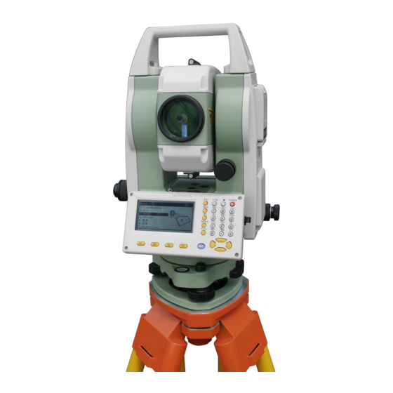
RTS/OTS680 Series
Total Station Instruction Manual
RTS682/RTS685(L)
OTS682-R300/R500/R1000
OTS685-R300/R500/R1000
Ver: 2.1.1e(2014-01)
Suzhou FOIF Co., Ltd.
1
Table of
Contents
Previous
Page
Next
Page
1
2
3
4
5
Advertisement
Table of Contents
Need help?
Do you have a question about the RTS680 Series and is the answer not in the manual?
Ask a question
Questions and answers
Related Manuals for Foif RTS680 Series
Measuring Instruments Foif J2-2 Instruction Manual
Optical theodolite (28 pages)
Measuring Instruments Foif OTS682-R500 Instruction Manual
(144 pages)
This manual is also suitable for:
Ots680 series
Rts682
Rts685
Ots682-r300
Ots682-r500
Ots682-r1000
...
Show all
Ots685-r300
Ots685-r500
Ots685-r1000
Table of Contents
Save PDF
Print
Rename the bookmark
Delete bookmark?
Delete from my manuals?
Login
Sign In
OR
Sign in with Facebook
Sign in with Google
Upload manual
Upload from disk
Upload from URL


Need help?
Do you have a question about the RTS680 Series and is the answer not in the manual?
Questions and answers