Table of Contents
Advertisement
Quick Links
FEATURES
Simple & fast integration with development
kits and sample iOS & Android API
Built-in reliable Connection based mesh to
support large data packets, Mesh Network
(Node and Bridge) for Android
Long-range, module connectivity up to 120
meters
Compact form factor 17.4mm X 20.4mm X
3mm
Castellated SMT pads for easy and reliable
PCB mounting
Over the Air firmware update from one
device to an entire network
32-bit ARM® Cortex™ M0 nRF51822 CPU
Proximity support for beacon and location
based services
No. of GPIOs available for user - 26
Configurable I/O mapping for analog and
digital
Simultaneous master and slave operation
Certifications: FCC, IC, CE and BT SIG
RoHS compliant
OPERATIONAL
Operating voltage range: 1.8V to 3.6VDC
Temperature range: -25°C to 75°C
Low-power consumption
Interface: SPI, UART, I2C and 8/9/10bit ADC
256KB flash and 32KB RAM
APPLICATIONS
Health & Fitness Equipment
Lighting – bulbs and fixtures
Automotive
Home Automation
Power plugs, routers
Internet of Things (IoT) Sensor tag
AV consoles, game controllers
Industrial Control
© ilumi Solutions Inc
.
................
®
Bluetooth
4.0 Low Energy Module
www.ilumisolutions.com
MeshTek-H51
MESHTEK-H51 Bluetooth 4.0 Low
Energy Module
DESCRIPTION
With the smartest and most robust Bluetooth
Mesh Network technology on the market, ilumi's
MeshTek provides an elegant and affordable
solution for manufacturers looking to quickly and
reliably bring BLE enabled IoT products to market.
The MESHTEK-H51 Smart Mesh Module reduces
development time, lowers manufacturing costs,
saves board space, eases certification and
minimizes the RF expertise required. This complete
platform solution includes software drivers,
sample
applications,
documentation, and a world-class support.
The MESHTEK-H51 internal controller to be used
for applications up to 16KB/32KB flash without the
need for external host MCU or software
development tools.
API
guide,
user
P a g e
1 | 12
Advertisement
Table of Contents

Related Manuals for iLumi MeshTek-H51

Summary of Contents for iLumi MeshTek-H51
- Page 1 Operating voltage range: 1.8V to 3.6VDC Temperature range: -25°C to 75°C The MESHTEK-H51 internal controller to be used Low-power consumption for applications up to 16KB/32KB flash without the Interface: SPI, UART, I2C and 8/9/10bit ADC need for external host MCU or software ...
-
Page 2: Table Of Contents
It is our intention to provide our valued customers with the best documentation possible to ensure successful use of your ilumi Solutions Inc products. To this end, we will continue to improve our publications to better suit your needs. Our publications will be refined and enhanced as new volumes and updates are introduced. -
Page 3: Device Overview
MESHTEK-H51 1. DEVICE OVERVIEW The MESHTEK-H51 Bluetooth Low Energy RF module integrates Bluetooth 4.0 radio baseband, 32-bit MCU, digital analog I/O, onboard stack. Figure 1 shows the module’s Block diagram. Figure 2 shows the module’s pinout and the description is shown in Table 1. - Page 4 Connection for 32.768 kHz crystal or external 32.768 Analog input kHz clock reference P0.28 Digital I/O General purpose I/O pin Note: For more details, check out nRF51822 (Package: QFAC) Cortex ARM M0 controller specifications P a g e 4 | 12 ilumi solutions, inc. www.ilumisolutions.com...
-
Page 5: General Specifications
+18.9dBm output Transmit Current 66mA Power Receive Current 24.84mA Radio RX Active ARM CPU Running Current 4.1mA No Radio Active No Radio and GPIO ARM CPU Ideal Current 2.6uA active P a g e 5 | 12 ilumi solutions, inc. www.ilumisolutions.com... -
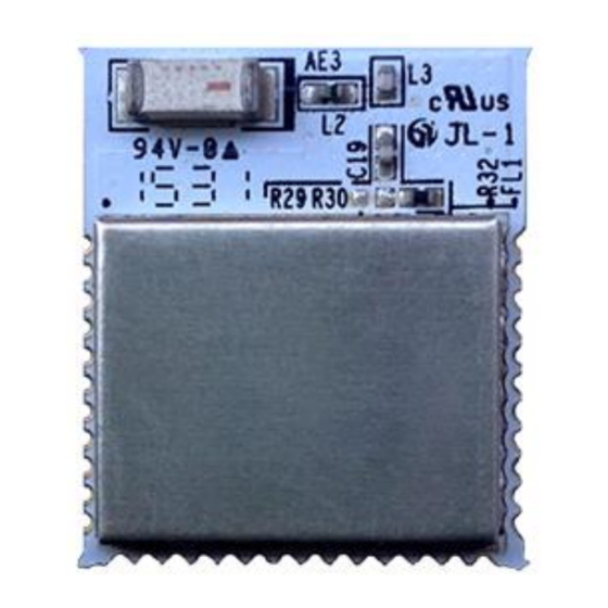
Page 6: Physical Dimensions
MESHTEK-H51 3. PHYSICAL DIMENSIONS Figure 3 shows the Top and Bottom for MESHTEK-H51 module. Figure 4 shows the recommended PCB layout. Figure 3: MESHTEK-H51 MODULE TOP AND BOTTOM VIEW Bottom View Top View Figure 4: MESHTEK-H51 RECOMMENDED PCB FOOTPRINT 17.1990... - Page 7 MESHTEK-H51 When laying out the carrier board for the MESHTEK-H51 module, the areas under the antenna, RF text point (semi-circular pad) and shielding connections should not have surface traces, ground planes, or exposed vias. Figure 5 shows the recommended mounting details and acceptable positioning of the MESHTEK-H51 on the host PCB.
-
Page 8: Solder Reflow Profile
E. Zone E: Cooling: The cooling rate should be fast to keep the solder grains small which will give a longer lasting joint. A typical cooling rate is 4°C/s P a g e 8 | 12 ilumi solutions, inc. www.ilumisolutions.com... -
Page 9: Regulatory Approval
MESHTEK-H51 5. REGULATORY APPROVAL 5.1. European Union regulatory compliance The MESHTEK-H51 module conforms to the product specifications listed in below Table 3. Table 3: MESHTEK-H51 European Compliance Testing Report Certification Standards Article Laboratory Date Number Safety EN 60950-1:2006 (2ND Edition) & IEC 60950-1:2005 [3.1(a)]... -
Page 10: Ic Compliance
5.2.4. OEM RESPONSIBILITIES TO COMPLY WITH FCC AND INDUSTRY CANADA REGULATIONS The MESHTEK-H51 Module has been certified for integration into products only by OEM integrators under the following conditions: This device is granted for use in configurations in which the antennas used for this transmitter must be installed to provide a separation distance of at least 20cm from all person and not be co-located with any other transmitters except in accordance with FCC and Industry Canada multi-transmitter product procedures. -
Page 11: Oem Labeling Requirements For End Product
(including the transmitter) and obtaining a separate FCC and Industry Canada authorization. 5.2.5. OEM Labeling requirements for end product For an end product using the MESHTEK-H51 module there must be a label containing, at least, the following information: This device contains... - Page 12 Corrected dimension of the board on Page no. 1 Corrected operating temperature range of the module on Page no. 1 Feb 2017 Updated certification information (Section 5) Updated Table of Contents Updated Table 2 Electrical specification P a g e 12 | 12 ilumi solutions, inc. www.ilumisolutions.com...
- Page 13 Mouser Electronics Authorized Distributor Click to View Pricing, Inventory, Delivery & Lifecycle Information: ilumi MTH51M01...
Need help?
Do you have a question about the MeshTek-H51 and is the answer not in the manual?
Questions and answers