Table of Contents
Advertisement
Quick Links
Advertisement
Table of Contents

Related Manuals for RAMVAC OWL

Summary of Contents for RAMVAC OWL
- Page 1 (On Wall Logic) User Guide Installation...
- Page 2 RAMVAC manufactured utility room equipment. Everything you need to install, operate and program your OWL is found in this manual, so here is all you need to do to get started: Take a few minutes to read the OWL Overview and OWL Features sections of this manual, to learn mor about the capabilities of the OWL.
-
Page 3: Table Of Contents
User Gude Table of Contents OWL User Interface Page 1 OWL and Compatible Controls Page 2 OWL Overview Page 3 OWL Feature Page 3 System Schematics Page 4-5 Electrical Connections Page 6 Operation and Monitoring Main Level Operation Page 8-9... -
Page 4: Owl And Compatible Controls
C1 Control S1 Electrols C1 Control – Mounted controls on the CustomAir air compressor and OWL – Mounted controls on the RAMVAC vacuum by RAMVAC communicates with the OWL. pumps and communicates with the OWL. Page 2 SOF_7.2.3-02-152... -
Page 5: Owl Overview
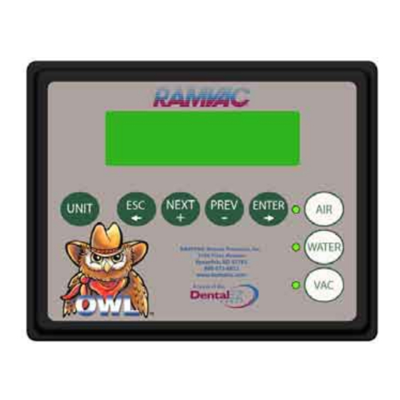
When used in conjunction with RAMVAC electronic controls, the OWL provides monitor- ing, control, and displays alarms. The OWL is also flexible enough to provide start/stop functions for all other brands of utility room equipment. The compact, attractive, easy to mount control panel features an easy to read LCD screen, equipment control buttons, program navigation buttons, and LED indicator lights. -
Page 6: System Schematics
Typical applications Thick (Black) Solid Line - Communication wires (3 – 18 ga. wires) shown Dashed (Blue) Line – Other wiring Schematic 1: OWL and RAMVAC equipment (with water valve option) Note: Transformer supplied with Interface Control C1 Control Interface Control... - Page 7 User Gude Schematic 3: OWL and multiple RAMVAC controls (with water valve option and autowash) Note: Transformer supplied with Interface Control S1 Electrols Node Designation on top S1 Electrols S1 Electrols C1 Control Node Designation on top C1 Control C1 Control...
-
Page 8: Electrical Connections
The OWL requires a 12v DC power source to operate. On most systems (see Schematic 1) the power source can be either the S1 Electrols or the air compressor C1 Control. If using the S1 or C1 for power, connect the 5 terminal on the S1/C1 to the 5 terminal on the OWL and the 6 These wires can be included in the wire bundle with the communication wires, but terminal on the S1/C1 to the 6 terminal on the OWL. - Page 9 User Gude Notes SOF_7.2.3-02-152 Page 7 Effective date: 30-May-08...
-
Page 10: Operation And Monitoring
Maximum 4 presses on the esc button takes you back to the top level Press Esc button Press Enter button RAMVAC *** Screen shows for 3 seconds on power-up*** 1.00 RAMVAC OWL UNIT IN FAULT (enter) See Unit Staus ALL UNITS NORMAL ENTR FOR DETAILS... - Page 11 User Gude Main Level Descriptions 1. When power is applied, the OWL will show the OWL name and the revision number for 3 seconds. 2. After self test the OWL display will show one of the following 2 screens. a. ALL UNITS NORMAL All units connected are in the normal run or standby condition.
- Page 12 OPERATION AND MONITORING User Gude Unit Status Flow Chart A=AVAIL M=MAINT UNIT STATUS (enter) UNIT STATUS (enter) F=FAULT R=RUN Screen shows for 3 secs. (enter) UNIT IN FAULT ENTR FOR DETAILS Enter will show1 of the Use Prev and Next following 4 options buttons to move cursor V1 MODE:...
- Page 13 The letters A,R,F below each number gives the status of the equipment selection in the system, corresponding to the number above it. Note: The OWL only shows the equipment configured in the system. Next or Prev arrow keys on the keypad to toggle the equipment selection.
- Page 14 OPERATION AND MONITORING User Gude System Status Flow Chart (enter) VACUUM SYSTEM HR DETAIL (enter) SYSTEM STATUS (enter) HOURS RUN WITH SYSTEM STATUS UNITS HOURS RUN WITH (prev button) UNITS Next or Prev buttons toggles the number of system units FAULT HISTORY (enter) UNIT #1...
- Page 15 System Status Description SYSTEM STATUS a. Enter from the keypad gives the SYSTEM HOUR DETAIL screen. b. Esc from the keypad returns to OWL startup screen. 2. VACUUM SYSTEM STATUS a. Enter from the keypad produces the SYSTEM HOUR DETAIL screen.
- Page 16 OPERATION AND MONITORING User Gude OWL Configuration Flow Chart OWL CONFIGURATION (enter) OWL LIFETIME HOURS ON (prev button) REVISION 1.00 (prev button) EDIT NODES (prev button) (enter) SYSTEM SHUTDOWN SYSTEM SHUTDOWN NONE DELAY = NONE HR DELAY = Next or Prev buttons toggles the hours...
- Page 17 OPERATION AND MONITORING User Gude OWL Configuration Description 1. OWL CONFIGURATION Enter from the keypad produces the number of run hours over the OWL lifetime. Select Prev Button 2. REVISION Gives the revision number of the OWL. Select Prev Button 3.
- Page 18 NOTES User Gude Page 16 SOF_7.2.3-02-152 Effective date: 30-May-08...
- Page 19 NOTES User Gude SOF_7.2.3-02-152 Page 17 Effective date: 30-May-08...
-
Page 20: Multiple Unit System
S1 Electrols or C1 Controller already in the system. On systems without an S1 or C1, a wall transformer provides power for the OWL Controller. In the system, the OWL is connected to one of the S1 Electrols mounted to one of the vacuum units or to one of the C1 Controls mounted to one of the CustomAir compressors. -
Page 21: Low Voltage Electrical Connections
(1). These wires can be included in the wire bundle with the communication wires, but will be connected to only one of the RAMVAC equipment controls in the system. (2). A separate transformer is used on OWL only if the 12VDC is not supplied by the S1 or C1. SOF_7.2.3-02-152... -
Page 22: System Layout For 2 Units
MULTIPLE UNIT SYSTEMS User Gude System layout for 2 Units Vacuum Pressure Switch Wired to S1 Electrols Node 1 Breaker Panel 2 wires 5 wires Disconnect Disconnect 3 wires Page 20 SOF_7.2.3-02-152 Effective date: 30-May-08... -
Page 23: System Layout For 3-8 Units
MULTIPLE UNIT SYSTEMS User Gude System layout for 3 to 8 Units Simply add the unit power and the communication wires for up to 8 units. Thick (Black) Solid Line Line Voltage Thin (Red) Solid Line Low Voltage Wires Disconnect Disconnect 3 wires 3 wires... -
Page 24: Adjusting Vacuum Pressure
WARNING: You can damage equipment by making improper vacuum controller adjustments. Do not exceed motor full load amperes. Please contact RAMVAC if you are at all uncertain about this adjustment. Adjusting the Vacuum Controller 1. Close all vacuum valves (high volume evacuators, saliva ejectors, surgical suctions) and close any other treatment room vacuum de- vices (nitrous oxide scavengers, vacuum sinks, vacuum cuspidors). -
Page 25: Overhead Piping Adjustments
Vacuum Pressure Switch,” on previous page. 10 feet 10.2” Hg Warning: Do not exceed motor full load amperes. Please contact 11 feet 11.0” Hg RAMVAC if you are at all uncertain about this adjustment. 12 feet 12.0” Hg SOF_7.2.3-02-152 Page 23 Effective date: 30-May-08... - Page 26 NOTES User Gude Page 24 SOF_7.2.3-02-152 Effective date: 30-May-08...
-
Page 27: Ramvac Product Support Services
*When installed, operated and maintained in accordance with written instructions. RAMVAC, Bison, Bulldog, FLOWCHECK, Ramclean and VACHECK are registered trademarks and InfiniTank, OWL and SlugBuster are trademark of RAMVAC Dental Products, Inc. SOF_7.2.3-02-152 Inside Back Cover... - Page 28 (800) 5-RAMVAC FAX (605) 642-3776 www.ramvac.com © 2008 RAMVAC Dental Products All rights reserved. No part of this publication may be copied or distributed, transmitted or transcribed in any form or by any means without the expressed written permission of RAMVAC Dental Products, Spearfish, SD 57783...
Need help?
Do you have a question about the OWL and is the answer not in the manual?
Questions and answers