Advertisement
Quick Links
Thank you for purchasing the M4x Blade.
When unpacking your M4x Blade confirm the following items
were received with your shipment.
Software CD
This CD also includes the User Manual
AC Power Supply Adapter
120/240 VAC, 12 VDC 2.5 Amp regulated
(Note: on units powered from a DC source, this item
will not be included)
Power Cord
(Note: on units powered from a DC source, this item
will not be included)
USB Cable
If any of these items are missing, please contact Sales at
775-858-2400, press 2.
Installing The M4x Software
Note: Install this software before plugging in the M4x Blade.
1.
Uninstall old M4x Software before installing a new version.
2.
Install the software by inserting the CD into the computer's
CD Drive.
3.
We recommend selecting "Easy Install" when prompted.
4.
Follow the on-screen prompts to complete the installation.
5.
Refer to the M4x User Manual included on the software disk
for more detailed installation instructions, (especially if this
version of software will be installed over a prior version of
software).
Powering Up the M4x Blade
1.
Connect the Power Cable into the AC Power Adapter.
2.
Connect the AC Power Adapter to your AC power source
(e.g. 3-pronged grounded wall outlet). The AC Power
Adapter can be connected to a 100 to 240 VAC, 50-60 Hz,
0.5A source.
3.
Connect the DC plug from the AC Power Adapter into the
DC jack on the rear of the M4x Blade as shown in Figure 1.
DC Jack
Raven Electronics Corporation 4655 Longley Lane, Reno, NV 89502
M4x Blade Quick Start Guide
Please Read Before You Start
USB Port
Figure 1
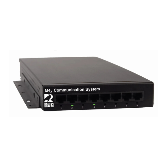
There are seventeen LED indicators on the front panel of the
M4x Blade as shown in Figure 2.
There are two LEDs per Port. The first LED is Red (default is
XMT (Output)). The second LED is Green (default is RCV
(Input)).
There is a Power On LED which is also Green to let the user
know the M4x Blade is powered on.
For more details regarding how the LEDs can be set to indicate
COR (E-Lead) or PTT (M-Lead), please refer to the M4x User
Manual.
On top of each M4x Blade, there are labels with pin out
information for each port installed in the M4x Blade. Please
note, the pin order is grouped for clarity.
1 2 3 4 5 6 7 8
WWW.RAVENCOMM.COM
MODULE 476-152 2-WIRE INTERFACE
PIN 1
PIN 1
2WIRE
2WIRE
PIN 2
PIN 2
PIN 3
PIN 3
M-LEAD
M-LEAD
PIN 6
PIN 6
PIN 4 = NC
PIN 4 = NC
PIN 5 = NC
PIN 5 = NC
PIN 7
PIN 7
E-LEAD
E-LEAD
PIN 8
PIN 8
MODULE 476-178
RELAY OPT – 02
PIN 1 = RLY 1 COM
PIN 1 = RLY 5 COM
PIN 2 = RLY 1 NO
PIN 2 = RLY 5 NO
PIN 3 = RLY 2 COM
PIN 3 = RLY 6 COM
PIN 4 = RLY 2 NO
PIN 4 = RLY 6 NO
PIN 5 = RLY 3 COM
PIN 5 = RLY 7 COM
PIN 6 = RLY 3 NO
PIN 6 = RLY 7 NO
PIN 7 = RLY 4 COM
PIN 7 = NC
PIN 8 = RLY 4 NO
PIN 8 = NC
Main: 775.858.2400 Sales: Press 2 Technical Support: Press 3
www.ravencomm.com
LED Indicators
Figure 2
M4x Port Pin Outs
Note: E-Lead is COR, M-Lead is PTT
MODULE 476-150 4-WIRE INTERFACE
MODULE 476-151 4-WIRE INTERFACE
PIN 1
PIN 1
PIN 1
RCV
RCV
RCV
PIN 2
PIN 2
PIN 2
PIN 3
PIN 3
PIN 3
M-LEAD
M-LEAD
M-LEAD
PIN 6
PIN 6
PIN 6
PIN 4
PIN 4
PIN 4
XMT
XMT
XMT
PIN 5
PIN 5
PIN 5
PIN 7
PIN 7
PIN 7
E-LEAD
E-LEAD
E-LEAD
PIN 8
PIN 8
PIN 8
MODULE 476-175
SNI
MODULE 476-178
PIN 1 = NC
PIN 1 = NC
PIN 1 = RLY 1 NC
PIN 2 = NC
PIN 2 = NC
PIN 2 = RLY 1 COM
PIN 3 = NC
PIN 3 = NC
PIN 3 = RLY 1 NO
PIN 4
PIN 4 =
PIN 4 = RLY 2 NC
PSTN
PSTN
PIN 5
PIN 5 =
PIN 5 = RLY 2 COM
PIN 6 = NC
PIN 6 = NC
PIN 6 = RLY 2 NO
PIN 7 = NC
PIN 7 = NC
PIN 7 = NC
PIN 8 = NC
PIN 8 = NC
PIN 8 = NC
MODULE 476-180
I/O
MODULE 476-777
PIN 1 = I/O 1
PIN 1 = I/O 9
PIN 1
ETH XMT
PIN 2 = I/O 2
PIN 2 = I/O 10
PIN 2
PIN 3 = I/O 3
PIN 3 = I/O 11
PIN 3
ETH RCV
PIN 4 = I/O 4
PIN 4 = I/O 12
PIN 6
PIN 4
PIN 5 = I/O 5
PIN 5 = I/O 13
ETH SHLD
PIN 5
PIN 6 = I/O 6
PIN 6 = I/O 14
PIN 7
PIN 7 = I/0 7
PIN 7 = I/0 15
ETH SHLD
PIN 8
PIN 8 = I/O 8
PIN 8 = I/O 16
Fax: 775.858.2410
PIN 1
RCV
PIN 2
PIN 3
M-LEAD
PIN 6
PIN 4
XMT
PIN 5
PIN 7
E-LEAD
PIN 8
RELAY
PIN 1 = RLY 3 NC
PIN 2 = RLY 3 COM
PIN 3 = RLY 3 NO
PIN 4 = RLY 4 NC
PIN 5 = RLY 4 COM
PIN 6 = RLY 4 NO
PIN 7 = NC
PIN 8 = NC
VOIP
PIN 1
4W RCV
PIN 2
PIN 3
M-LEAD
PIN 6
PIN 4
4W XMT/2W
PIN 5
PIN 7
E-LEAD
PIN 8
Advertisement

Related Manuals for Raven M4x


Summary of Contents for Raven M4x
- Page 1 PIN 7 = NC PIN 7 PIN 7 = NC PIN 7 = NC PIN 7 = NC DC jack on the rear of the M4x Blade as shown in Figure 1. E-LEAD E-LEAD PIN 8 PIN 8 = NC...
- Page 2 Verify the M4x Blade is powered on Configure the M4x Analog 4-Wire Module(s) before configuring a Bridge. Connect the USB Cable to the M4x Blade as well as to the computer The M4x Blade allows multiple bridge configurations to be created on one blade.
Need help?
Do you have a question about the M4x and is the answer not in the manual?
Questions and answers