Table of Contents
Advertisement
Quick Links
Rev:
1.00
AIMMS-20
Date:
11.22.2013
OPERATING MANUAL
Page: 1 of 40
Document-P/N:
AIMMS20-OM
AIMMS-20
Aircraft Integrated Meteorological
Measurement System
OPERATING MANUAL
Document-P/N: AIMMS20-OM
Aventech Research Inc.
110 Anne Street South, Unit 23
Barrie, Ontario, Canada L4N 2E3
Tel: (705) 722-4288
Fax: (705) 722-9077
Web:
www.aventech.com
© Aventech Research Inc. 2013. All Rights Reserved.
Advertisement
Table of Contents

Related Manuals for Aventech AIMMS-20

Summary of Contents for Aventech AIMMS-20
- Page 1 Aircraft Integrated Meteorological Measurement System OPERATING MANUAL Document-P/N: AIMMS20-OM Aventech Research Inc. 110 Anne Street South, Unit 23 Barrie, Ontario, Canada L4N 2E3 Tel: (705) 722-4288 Fax: (705) 722-9077 Web: www.aventech.com © Aventech Research Inc. 2013. All Rights Reserved.
- Page 2 Date Name Signature Function 22.11.2013 Bruce H. Woodcock Customer Approval (as required) Date Name Signature Function Table of Functions CUST Customer Design Engineer Head of Design Engineering Production Manager Quality Manager © Aventech Research Inc. 2013. All Rights Reserved.
- Page 3 NOTICES WARRANTY Aventech Research Inc. products are warranted to be free from defects in material and workmanship under normal use and service for a period of one year beginning on the date of shipment. This warranty extends only to the original buyer or end-user customer of an Aventech Research Inc.
- Page 4 LOSSES, INCLUDING LOSS OF DATA, ARISING FROM ANY CAUSE OR THEORY. COPYRIGHT © Aventech Research Inc. 2013. No part of this manual may be reproduced in any form or by any means (including electronic storage and retrieval or translation into a foreign language) without prior agreement and written consent from Aventech Research Inc.
- Page 5 1.00 AIMMS-20 Date: 11.22.2013 OPERATING MANUAL Page: 5 of 40 Document-P/N: AIMMS20-OM RECORD OF REVISIONS Firmware Date Issue Page Paragraph Comments Revision 21.11.2013 1.00 Preliminary Draft 22.11.2013 1.00 Release © Aventech Research Inc. 2013. All Rights Reserved.
-
Page 6: Table Of Contents
1 INTRODUCTION ........................8 2 SYSTEM OVERVIEW ......................9 2.1 Air Data Probe (ADP) ........................... 9 2.2 Inertial Measurement Unit (IMU) ..................... 10 2.3 GPS Phase Module (GPS) ........................ 11 2.4 Central Processing Module (CPM) .................... 12 2.5 Communications .......................... 13 3 AIMMS-20 SETUP AND CALIBRATION ................14 3.1 Preparation of Laptop / Computer .................... 14 3.2 Measurements .......................... 14 3.3 Calibration Flight Procedure ...................... 15 3.3.1 Pre‐Flight Procedure ........................ 15 3.3.2 Aerodynamic Calibration Manoeuvres .................. 15 3.3.3 Inertial System Calibration Manoeuvres .................. 17 3.3.4 Post Flight Procedure ......................... 18 4 AIMMS CONFIGURATION UTILITY SOFTWARE USER’S MANUAL (aimcfg.exe) ..... 19 ... - Page 7 5.3 CENTRAL PROCESSING MODULE (CPM) .................... 31 5.4 METEOROLOGICAL .......................... 32 5.4.1 Temperature .......................... 32 5.4.2 Relative Humidity ........................ 32 5.4.3 Three‐Dimensional Wind ...................... 32 5.5 ELECTRICAL ............................ 32 5.6 ENVIRONMENTAL .......................... 33 5.7 WEIGHT ............................. 33 APPENDIX A: AIMMS-20 SERIAL COMMUNICATION FORMAT ..........34 A.1 Introduction ............................ 34 A.2 Hardware Configuration ........................ 34 A.3 Packet Format ........................... 34 A.3.1 Data Block, Standard Meteorology Packet (ID = 0) .............. 35 A.3.2 Data Block, Aircraft‐State Data Packet (ID = 1) ................ 36 A.3.3 Data Block, Purge Flow Packet (ID = 4) .................. 37 A.3.4 Data Block, Internal Probe Temperature Packet (ID = 5) ............ 37 A.3.5 Data Block, CAN Message Forwarding (Raw Data) Packet (ID = 22) .......... 38 ...
-
Page 8: Introduction
In order to set up and calibrate the system, the user will utilize Aventech’s aimcfg PC-based software utility. A user’s guide for the aimcfg software utility is provided in Section 4. -
Page 9: System Overview
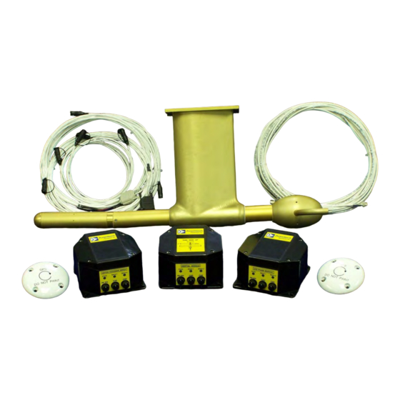
With your AIMMS-20 system you will have received one of two Air Data Probe types depending on the airframe for the planned installation, an under-wing version as shown in Figure 1 or a sting-mount version as shown in Figure 2. -
Page 10: Inertial Measurement Unit (Imu)
However, the compromise is that MEMS-based measurement devices have poorer long term DC stability. The AIMMS-20 system compensates for this DC instability using a single-axis GPS carrier-phase system which is described in Section 2.3. -
Page 11: Gps Phase Module (Gps)
IMU described in Section 2.2. The mathematical algorithm used to optimally combine the two sets of data is called an Extended Kalman Filter (EKF) and runs in the firmware loaded in the CPM described in Section 2.4. © Aventech Research Inc. 2013. All Rights Reserved. -
Page 12: Central Processing Module (Cpm)
The CPM also acts as the main interface between the aircraft spray navigation system and the rest of the AIMMS-20. Aircraft power is provided to the AIMMS-20 through the CPM module which steps the input voltage down +12 VDC and distributes it to power the balance of the modules through the Controller Area Network (CAN) cables. -
Page 13: Communications
Figure 5: AIMMS-20 Central Processing Module 2.5 Communications The four AIMMS-20 modules communicate with each other via a high-speed, digital serial Controller Area Network (CAN) bus. The four conductor cable connected between the modules provides power to each of the modules and communication between them. -
Page 14: Aimms-20 Setup And Calibration
3 AIMMS-20 SETUP AND CALIBRATION 3.1 Preparation of Laptop / Computer The first step in setting up your AIMMS-20 system is to install the aimcfg software utility provided with the system onto a laptop computer which will be used to interact with the system. -
Page 15: Calibration Flight Procedure
The resulting data file provides the required information so that the calibration coefficients that have to be programmed into the AIMMS-20 can be determined in order to provide a real-time wind solution. Two different procedures exist for flight calibration. The first procedure is required to determine aerodynamic errors induced by the aircraft itself (see Section 3.3.2). - Page 16 Perform the yaw manoeuvre at the operational TAS setting. xi) Decrease the airspeed once again continuously to the lowest airspeed. xii) Perform one last set of yaw manoeuvres at the lowest airspeed. © Aventech Research Inc. 2013. All Rights Reserved.
-
Page 17: Inertial System Calibration Manoeuvres
When complete stabilize on the original heading for approximately 5 seconds. iii) Repeat step ii) using an approximate bank angle of 30 degrees. iv) Repeat step ii) again using an approximate bank angle of 45 degrees. © Aventech Research Inc. 2013. All Rights Reserved. -
Page 18: Post Flight Procedure
E-mail the log file on the USB FLASH memory device to support@aventech.com or the e-mail address of your dedicated Aventech support engineer for post- processing. The new calibration parameters will be e-mailed to you for programming into the AIMMS-20 system. -
Page 19: Aimms Configuration Utility Software User'smanual (Aimcfg.exe)
Connect the DSub-9 connector labelled COM1 with a black hood to your computer at this point in order to communicate with, and setup, the AIMMS-20. Once the communications cable is connected, and the AIMMS system connected to power, turn on the AIMMS. - Page 20 1) Check all connections, including that you are connected to COM1 (black hood) on the serial cable. 2) Make sure the unit has power applied. 3) Check that the correct baud rate is set. Click “OK” to continue. © Aventech Research Inc. 2013. All Rights Reserved.
-
Page 21: Main Program Window
When the Log Download menu item is selected, a dialog box appears indicating the file name used for storing the data log (generated based on date and time) and the © Aventech Research Inc. 2013. All Rights Reserved. - Page 22 (60 s.). © Aventech Research Inc. 2013. All Rights Reserved.
-
Page 23: Error Log Download
Section 4.2). 4.4.3 View Broadcast Data Aircraft state and meteorological data is computed in real-time by the AIMMS-20 and broadcast out the COM2 port of the CPM (grey hooded DSub-9 connector on the provided serial cable. If this serial port is connected to your computer, it is possible to view this information directly in real-time as shown below, e.g. -
Page 24: Raw Data Capture
“raw” data. Selecting this menu item starts the collection of all sensor information that is passed between the four modules of the AIMMS-20 system via the COM2 serial port of the CPM connected to your computer. A dialog box will be displayed showing the filename being used to record the data, and the number of bytes currently transferred. -
Page 25: Update Firmware
4.4.6 Update Firmware The AIMMS-20 CPM firmware is field upgradable. Updating the CPM’s internal firmware is performed using the “Update Firmware” menu item and is described below. Simply follow the instructions provided by the aimcfg software. - Page 26 Once the user has selected the firmware update file using the “Open” button, a dialog box will be displayed instructing the user to insure the AIMMS-20 is powered down. Press OK once you have verified that the system is OFF.
-
Page 27: Setup
The process from power reset to completion should take a few minutes. 4.5 Setup The “Setup” menu item displays a window which allows the user to enter and program general operational parameters for the AIMMS-20 system. These parameters include: 1) Internal data log status and period ... -
Page 28: Air Data Calibration Parameters
AIMMS20-OM After the data is downloaded, an AIMMS-20 Setup Form is displayed showing the setup parameters currently stored in the system. When the setup information is downloaded for the first time, it will consist of factory defaults settings which were programmed into the system at time of manufacture. -
Page 29: Cross-Axis Alignment Errors
These parameters are obtained by analysis of flight data obtained during special calibration maneuvers (see Section 3.3) and will be provided to the end user by Aventech Research Inc. The dynamic heating efficiency parameter should always be set to 0.42 as this is a function of the air-data probe design and not subject to change. -
Page 30: Version
4.8 Version The “Version” menu item displays the version number of the aimcfg software currently installed on your computer. Click “OK” to continue. © Aventech Research Inc. 2013. All Rights Reserved. -
Page 31: Technical Specifications
40 Hz Measurement Range Accuracy 3-axis accelerations +/- 5g 0.005g 3-axis angular rates +/- 60 deg/s 0.03 deg/s 5.3 CENTRAL PROCESSING MODULE (CPM) Processor: Motorola DSP56F807 Internal FLASH Memory: 16 Mbit © Aventech Research Inc. 2013. All Rights Reserved. -
Page 32: Meteorological
5.5 ELECTRICAL Operating Voltage: 12.5 - 37 VDC Input Max. Operating Current: 900 mA @ 12.5 VDC Digital Interfaces: Controller Area Network (CAN2A) 500 kbps RS-232 Serial Ports (default 19.2 kbps) © Aventech Research Inc. 2013. All Rights Reserved. -
Page 33: Environmental
Air Data Probe (ADP): 3.36 kg (7.38 lb) Inertial Measurement Unit (IMU): 0.74 kg (1.63 lb) GPS Module (GPS): 0.80 kg (1.76 lb) Central Processing Module: 0.60 kg (1.32 lb) © Aventech Research Inc. 2013. All Rights Reserved. -
Page 34: Appendix A: Aimms-20 Serial Communication Format
APPENDIX A: AIMMS-20 SERIAL COMMUNICATION FORMAT A.1 Introduction The AIMMS-20 offers bi-directional RS-232 communications using a binary packet format. The default broadcast packet is called the Standard Meteorology Data Packet, which is output at a user-defined rate up to 20Hz. An optional Aircraft-State Data Packet is also available, which includes aircraft position, velocity, attitude and aircraft- relative flow (TAS) vector, each in three dimensions. -
Page 35: A.3.1 Data Block, Standard Meteorology Packet (Id = 0)
4) Wind speed and wind direction output are damped by a 20-point moving average (20 of the latest wind solution updates, eg. 5Hz update = 4 s damping). © Aventech Research Inc. 2013. All Rights Reserved. - Page 36 Vertical wind – msb Sideslip angle (deg) – lsb Sideslip angle - msb AOA pres. differential (dimensionless)-lsb AOA pres. differential – msb 10000 Sideslip differential (dimensionless) – lsb Sideslip differential – msb 10000 © Aventech Research Inc. 2013. All Rights Reserved.
- Page 37 Note: Low temperature threshold setting is the temperature below which the internal probe block heaters are engaged. The high threshold, i.e. temperature above which heaters are turned off, is always set to the low threshold + 10 Celsius. © Aventech Research Inc. 2013. All Rights Reserved.
- Page 38 Length of CAN msg. data segment, value 0 – 8 (bits b.14 – b.11) 25 + Message 9, CAN data byte 1 u/s short int 24 + Message 9, CAN data byte m u/s short int © Aventech Research Inc. 2013. All Rights Reserved.
- Page 39 AIMMS-20 Date: 11.22.2013 OPERATING MANUAL Page: 39 of 40 Document-P/N: AIMMS20-OM A.4 Packet-Based Command Input to AIMMS-20 CPM A.4.1 5-Hole Probe Purge Initiation Packet ID: # bytes, data block Byte # Description Var. Type Scale Purge period (ms) – lsb Purge period (ms) –...
- Page 40 ID5 (Internal Probe Temperature). The high threshold, i.e. temperature above which heaters are turned off, is always set to the low threshold + 10 Celsius. © Aventech Research Inc. 2013. All Rights Reserved.
Need help?
Do you have a question about the AIMMS-20 and is the answer not in the manual?
Questions and answers