Table of Contents
Advertisement
Quick Links
Rev:
1.00
AIMMS-20
Date:
11.11.2013
INSTALLATION MANUAL
Page: 1 of 48
Document-P/N:
AIMMS20-IM
AIMMS-20
Aircraft Integrated Meteorological
Measurement System
INSTALLATION MANUAL
Document-P/N: AIMMS20-IM
Aventech Research Inc.
110 Anne Street South, Unit 23
Barrie, Ontario, Canada L4N 2E3
Tel: (705) 722-4288
Fax: (705) 722-9077
Web:
www.aventech.com
© Aventech Research Inc. 2013. All Rights Reserved.
Advertisement
Table of Contents

Subscribe to Our Youtube Channel
Related Manuals for Aventech AIMMS-20

Summary of Contents for Aventech AIMMS-20
- Page 1 Aircraft Integrated Meteorological Measurement System INSTALLATION MANUAL Document-P/N: AIMMS20-IM Aventech Research Inc. 110 Anne Street South, Unit 23 Barrie, Ontario, Canada L4N 2E3 Tel: (705) 722-4288 Fax: (705) 722-9077 Web: www.aventech.com © Aventech Research Inc. 2013. All Rights Reserved.
- Page 2 Date Name Signature Function 11.11.2013 Bruce H. Woodcock Customer Approval (as required) Date Name Signature Function Table of Functions CUST Customer Design Engineer Head of Design Engineering Production Manager Quality Manager © Aventech Research Inc. 2013. All Rights Reserved.
- Page 3 NOTICES WARRANTY Aventech Research Inc. products are warranted to be free from defects in material and workmanship under normal use and service for a period of one year beginning on the date of shipment. This warranty extends only to the original buyer or end-user customer of an Aventech Research Inc.
- Page 4 LOSSES, INCLUDING LOSS OF DATA, ARISING FROM ANY CAUSE OR THEORY. COPYRIGHT © Aventech Research Inc. 2013. No part of this manual may be reproduced in any form or by any means (including electronic storage and retrieval or translation into a foreign language) without prior agreement and written consent from Aventech Research Inc.
- Page 5 1.00 AIMMS-20 Date: 11.11.2013 INSTALLATION MANUAL Page: 5 of 48 Document-P/N: AIMMS20-IM RECORD OF REVISIONS Firmware Date Issue Page Paragraph Comments Revision 31.10.2013 1.00 Preliminary Draft 11.11.2013 1.00 Release © Aventech Research Inc. 2013. All Rights Reserved.
-
Page 6: Table Of Contents
3.2 Inertial Measurement Unit (IMU) ..................... 18 3.3 GPS Phase Module (GPS) ........................ 20 3.3.1 GPS Antennas .......................... 20 3.3.2 GPS Phase Module ........................ 21 3.4 Central Processing Module (CPM) .................... 21 3.5 Electrical / Communications Wiring .................... 22 3.5.1 GPS Coaxial Antenna Cables ...................... 22 3.5.2 Controller Area Network (CAN) Cables .................. 22 3.5.3 Power Input Cable ........................ 23 3.5.4 RS‐232 Serial Communications Cable .................. 23 4 GROUND TEST PROCEDURE ..................... 24 4.1 Application of Power to the System .................... 24 4.2 Air Data Probe (ADP) ......................... 24 4.3 Inertial Measurement Unit (IMU) ..................... 24 4.4 GPS Phase Module (GPS) ........................ 24 4.5 Central Processing Module (CPM) .................... 25 © Aventech Research Inc. 2013. All Rights Reserved. - Page 7 AIMMS20-IM 5 INSTRUCTIONS FOR CONTINUED AIRWORTHINESS (ICA) ..........26 5.1 Pre‐Flight Checks .......................... 26 5.2 Operational Checks ........................... 26 5.3 Aircraft Maintenance Schedule ...................... 26 5.4 Troubleshooting .......................... 27 5.5 Service Removal .......................... 28 APPENDIX A: AIMMS-20 COMPONENT CAD DRAWINGS ............30 A.1 Under‐Wing Air Data Probe (ADP) .................... 31 A.2 Sting Mount Air Data Probe (ADP) .................... 34 A.3 Inertial Measurement Unit (IMU) ..................... 37 A.4 GPS Phase Module (GPS) and Antennas ................... 40 A.4.1 Sensor Systems S67‐1575‐39 GPS Antenna Datasheet ............. 43 A.4.2 ANTCOM 3G15A‐XT‐1 GPS Antenna Datasheet ................ 44 A.5 Central Processing Module (CPM) .................... 45 ...
-
Page 8: Introduction
RS-232 serial communications link to either a GPS navigation system or data acquisition system. This document provides a general description on how to install the AIMMS-20 on an airframe and engineering information to support the subsequent approval process with the appropriate certifying body. -
Page 9: System Component Descriptions
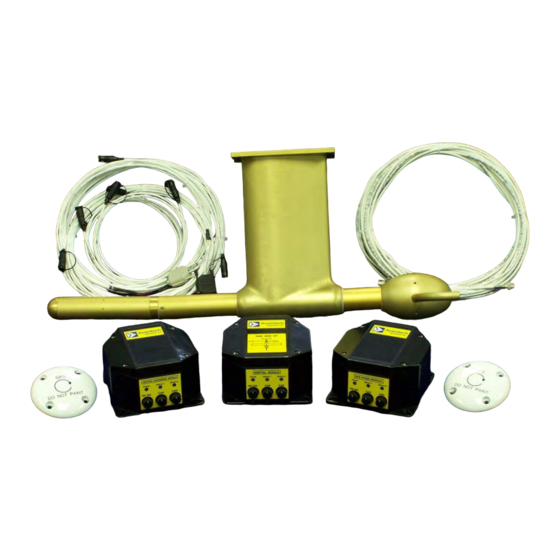
2 SYSTEM COMPONENT DESCRIPTIONS The AIMMS-20 system consists of four modules in total, an Air Data Probe (ADP) which is mounted external to the aircraft, an Inertial Measurement Unit (IMU), a GPS Phase Module (GPS) and a Central Processing Module (CPM). The following section of this manual lists the system components that should have arrived in your shipment and describes each of them in order to familiarize you with the system. -
Page 10: Air Data Probe (Adp)
With your AIMMS-20 system you will have received one of two Air Data Probe types depending on the airframe for the planned installation, an under-wing version as shown in Figure 1 or a sting-mount version as shown in Figure 2. - Page 11 INSTALLATION MANUAL Page: 11 of 48 Document-P/N: AIMMS20-IM Figure 3: AIMMS-20 Under-Wing Air Data Probe Installation Figure 4: AIMMS-20 Sting-Mount Air Data Probe Installation The under-wing ADP is typically utilized for fixed-wing installations while the sting- mount ADP is typically utilized in rotary-wing installations. In some cases end users have also used the sting-mount probe for fixed-wing installations with their own mounting bracket design.
-
Page 12: Inertial Measurement Unit (Imu)
However, the compromise is that MEMS-based measurement devices have poorer long term DC stability. The AIMMS-20 system compensates for this DC instability using a single-axis GPS carrier-phase system which is described in Section 2.4. -
Page 13: Central Processing Module (Cpm)
AIMMS-20, and the GPS navigation / data acquisition system and the AIMMS-20. The aircraft power is provided to the AIMMS-20 through the CPM module which steps the input voltage down +12 VDC and distributes it to the power the balance of the modules through the Controller Area Network (CAN) cables. -
Page 14: Communications
Figure 7: AIMMS-20 Central Processing Module 2.6 Communications The four AIMMS-20 modules communicate with each other via a high-speed, digital serial Controller Area Network (CAN) bus. The four conductor cable connected between the modules provides power to each of the modules and communication between them. -
Page 15: Installation Instructions
3.1 Air Data Probe (ADP) 3.1.1 Under-Wing Mount Air Data Probe The under-wing version of the AIMMS-20 ADP has an integrated pylon and mounting flange to accommodate mounting the probe to the lower surface of the wing (See Figures 3, 8 and 9). Detailed drawings of the ADP and ADP mounting flange are provided in Appendix A.1. -
Page 16: Sting-Mount Air Data Probe
3.1.2 Sting-Mount Air Data Probe The sting-mount version of the AIMMS-20 differs from the under-wing mount version in that the pylon has been eliminated and the electronics embedded in the pylon have been moved into a 12” longer measurement boom (36” rather than 24”... - Page 17 Figures 4, 10 and 11 provide examples of AIMMS-20 Sting-Mount ADP installations.
-
Page 18: Inertial Measurement Unit (Imu)
18.9 291.6 27.2 Table 2: Drag Force versus Airspeed for AIMMS-20 Sting-Mount ADP 3.2 Inertial Measurement Unit (IMU) The remaining three modules, the Inertial Measurement Unit (IMU), GPS Phase Module (GPS) and Central Processing Module (CPM), are all housed in octagonal fibreglass with 40% graphite filler enclosures. - Page 19 Examples of module installations are presented in Figures 12 and 13. Figure 12: AIMMS-20 IMU / GPS / CPM Module Installation Figure 13: AIMMS-20 IMU / GPS / CPM Module Installation ...
-
Page 20: Gps Phase Module (Gps)
/ fin. Examples of antenna installations are presented in Figures 14 and Mechanical drawings and technical specifications for the two 3.0” diameter GPS antennas that have been supplied with the AIMMS-20 system are provided in Appendix A.4. Figure 14: Fore / Aft GPS Antenna Installation ... -
Page 21: Gps Phase Module
Document-P/N: AIMMS20-IM Figure 15: AIMMS-20 Forward GPS Antenna Installation 3.3.2 GPS Phase Module Having the identical form factor as the IMU and CPM modules, four 0.25” wide slots are integrated into the base of the module to accommodate mounting it to the airframe using 10-32 or ¼-28 mounting fasteners. -
Page 22: Electrical / Communications Wiring
Aft antenna cable to the right TNC receptacle. 3.5.2 Controller Area Network (CAN) Cables Three CAN cables will have been provided with the AIMMS-20 kit, two 2’ cables and a third longer cable sized specifically for the airframe. These cables have HiRose HR30 series, 6 pin male plugs on both ends. -
Page 23: Power Input Cable
The AIMMS-20 power supply input accepts a wide range voltage input of 12.5 to 37 VDC. Current requirements are as follows: ... -
Page 24: Ground Test Procedure
4 GROUND TEST PROCEDURE The first step in assessing whether an AIMMS-20 has been properly installed in an aircraft involves powering the system for the first time and performing some initial observations and tests. The following of this document describes the observations and tests which can be conducted to verify that the system is operating correctly. -
Page 25: Document-P/N: Aimms20-Im
ADP, it is possible that it may also not be seeing messages from the IMU or GPS since the bus is checked for their messages subsequent to determining whether the ADP messages are present or not. © Aventech Research Inc. 2013. All Rights Reserved. -
Page 26: Instructions For Continued Airworthiness (Ica)
5 INSTRUCTIONS FOR CONTINUED AIRWORTHINESS (ICA) This section of the installation manual provides Instructions for Continued Airworthiness (ICA) of the Aventech Research Inc. AIMMS-20 airframe installation. It describes how you will maintain the airframe alteration of the aircraft airworthiness certificate. Specifically, instructions are included for appropriate pre-flight checks, operational checks, aircraft maintenance schedule including inspection of parts for wear and deterioration, troubleshooting procedures, and service removal. -
Page 27: Troubleshooting
Confirm AIMMS-20 breaker is engaged. f) Turn on Avionics Master switch. g) Check that the green power LED illuminates on all four AIMMS-20 modules (ADP, IMU, GPS, and CPM). If the power LED fails to illuminate on any of the four modules follow the Service Removal Instructions below for the failed module. -
Page 28: Service Removal
Status 1 LED should be green and cycling (blinking) once per second while the Status 2 LED should remain solid green. If the LEDs are solid red or cycling red please contact the Aventech Research Inc. technical support department and relay that information to them for further troubleshooting instructions. - Page 29 Page: 29 of 48 Document-P/N: AIMMS20-IM v) Contact Aventech Research Inc. Technical Support Department (see contact information below) and obtain an RMA number. GPS Installation: i) Unscrew and remove TNC connectors of the GPS antenna cables located at the rear of the module.
-
Page 30: Appendix A: Aimms-20 Component Cad Drawings
Rev: 1.00 AIMMS-20 Date: 11.11.2013 INSTALLATION MANUAL Page: 30 of 48 Document-P/N: AIMMS20-IM APPENDIX A: AIMMS-20 COMPONENT CAD DRAWINGS © Aventech Research Inc. 2013. All Rights Reserved. -
Page 31: A.1 Under-Wing Air Data Probe (Adp)
Rev: 1.00 AIMMS-20 Date: 11.11.2013 INSTALLATION MANUAL Page: 31 of 48 Document-P/N: AIMMS20-IM A.1 Under-Wing Air Data Probe (ADP) © Aventech Research Inc. 2013. All Rights Reserved. - Page 32 Rev: 1.00 AIMMS-20 Date: 11.11.2013 INSTALLATION MANUAL Page: 32 of 48 Document-P/N: AIMMS20-IM © Aventech Research Inc. 2013. All Rights Reserved.
- Page 33 Rev: 1.00 AIMMS-20 Date: 11.11.2013 INSTALLATION MANUAL Page: 33 of 48 Document-P/N: AIMMS20-IM © Aventech Research Inc. 2013. All Rights Reserved.
-
Page 34: A.2 Sting Mount Air Data Probe (Adp)
Rev: 1.00 AIMMS-20 Date: 11.11.2013 INSTALLATION MANUAL Page: 34 of 48 Document-P/N: AIMMS20-IM A.2 Sting Mount Air Data Probe (ADP) © Aventech Research Inc. 2013. All Rights Reserved. - Page 35 Rev: 1.00 AIMMS-20 Date: 11.11.2013 INSTALLATION MANUAL Page: 35 of 48 Document-P/N: AIMMS20-IM © Aventech Research Inc. 2013. All Rights Reserved.
- Page 36 Rev: 1.00 AIMMS-20 Date: 11.11.2013 INSTALLATION MANUAL Page: 36 of 48 Document-P/N: AIMMS20-IM © Aventech Research Inc. 2013. All Rights Reserved.
-
Page 37: A.3 Inertial Measurement Unit (Imu)
Rev: 1.00 AIMMS-20 Date: 11.11.2013 INSTALLATION MANUAL Page: 37 of 48 Document-P/N: AIMMS20-IM A.3 Inertial Measurement Unit (IMU) © Aventech Research Inc. 2013. All Rights Reserved. - Page 38 Rev: 1.00 AIMMS-20 Date: 11.11.2013 INSTALLATION MANUAL Page: 38 of 48 Document-P/N: AIMMS20-IM © Aventech Research Inc. 2013. All Rights Reserved.
- Page 39 Rev: 1.00 AIMMS-20 Date: 11.11.2013 INSTALLATION MANUAL Page: 39 of 48 Document-P/N: AIMMS20-IM © Aventech Research Inc. 2013. All Rights Reserved.
-
Page 40: A.4 Gps Phase Module (Gps) And Antennas
Rev: 1.00 AIMMS-20 Date: 11.11.2013 INSTALLATION MANUAL Page: 40 of 48 Document-P/N: AIMMS20-IM A.4 GPS Phase Module (GPS) and Antennas © Aventech Research Inc. 2013. All Rights Reserved. - Page 41 Rev: 1.00 AIMMS-20 Date: 11.11.2013 INSTALLATION MANUAL Page: 41 of 48 Document-P/N: AIMMS20-IM © Aventech Research Inc. 2013. All Rights Reserved.
- Page 42 Rev: 1.00 AIMMS-20 Date: 11.11.2013 INSTALLATION MANUAL Page: 42 of 48 Document-P/N: AIMMS20-IM © Aventech Research Inc. 2013. All Rights Reserved.
-
Page 43: A.4.1 Sensor Systems S67-1575-39 Gps Antenna Datasheet
Rev: 1.00 AIMMS-20 Date: 11.11.2013 INSTALLATION MANUAL Page: 43 of 48 Document-P/N: AIMMS20-IM A.4.1 Sensor Systems S67-1575-39 GPS Antenna Datasheet © Aventech Research Inc. 2013. All Rights Reserved. -
Page 44: A.4.2 Antcom 3G15A-Xt-1 Gps Antenna Datasheet
Rev: 1.00 AIMMS-20 Date: 11.11.2013 INSTALLATION MANUAL Page: 44 of 48 Document-P/N: AIMMS20-IM A.4.2 ANTCOM 3G15A-XT-1 GPS Antenna Datasheet © Aventech Research Inc. 2013. All Rights Reserved. - Page 45 Rev: 1.00 AIMMS-20 Date: 11.11.2013 INSTALLATION MANUAL Page: 45 of 48 Document-P/N: AIMMS20-IM A.5 Central Processing Module (CPM) © Aventech Research Inc. 2013. All Rights Reserved.
- Page 46 Rev: 1.00 AIMMS-20 Date: 11.11.2013 INSTALLATION MANUAL Page: 46 of 48 Document-P/N: AIMMS20-IM © Aventech Research Inc. 2013. All Rights Reserved.
- Page 47 Rev: 1.00 AIMMS-20 Date: 11.11.2013 INSTALLATION MANUAL Page: 47 of 48 Document-P/N: AIMMS20-IM © Aventech Research Inc. 2013. All Rights Reserved.
-
Page 48: A.6 Aimms-20 Wiring Diagram
Rev: 1.00 AIMMS-20 Date: 11.11.2013 INSTALLATION MANUAL Page: 48 of 48 Document-P/N: AIMMS20-IM A.6 AIMMS-20 Wiring Diagram © Aventech Research Inc. 2013. All Rights Reserved.
Need help?
Do you have a question about the AIMMS-20 and is the answer not in the manual?
Questions and answers