Table of Contents
Advertisement
INSTRUCTION MANUAL
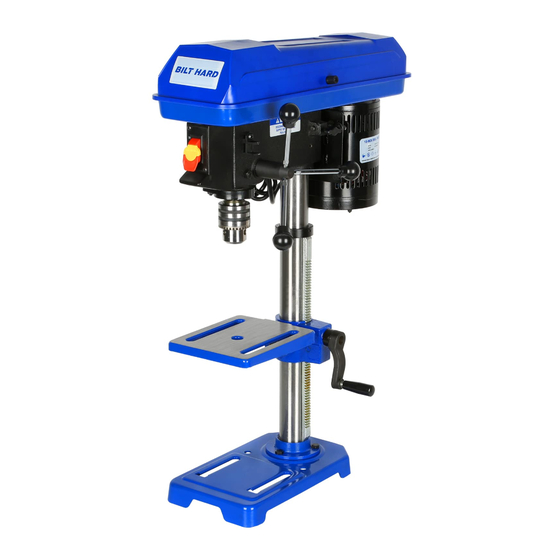
10-INCH DRILL PRESS
IMPORTANT : Your new tool has been engineered and manufactured to highest standards for dependability,
ease of operation, and operator safety. When properly cared for, this product will supply you years of rugged,
trouble-free performance. Pay close attention to the rules for safe operation, warnings, and cautions. If you use
your tool properly and for its intended purpose, you will enjoy years of safe, reliable service.
Thank you for ordering our product. If you have any issue, please email with
your order ID to inquiry@bilthardusa.com or call (888) 680-2849
Advertisement
Table of Contents

Related Manuals for BILT HARD 10-INCH

Summary of Contents for BILT HARD 10-INCH
- Page 1 INSTRUCTION MANUAL 10-INCH DRILL PRESS IMPORTANT : Your new tool has been engineered and manufactured to highest standards for dependability, ease of operation, and operator safety. When properly cared for, this product will supply you years of rugged, trouble-free performance. Pay close attention to the rules for safe operation, warnings, and cautions. If you use your tool properly and for its intended purpose, you will enjoy years of safe, reliable service.
-
Page 2: Table Of Contents
CONTENTS Introduction ..................... 3 Specifications ....................3 General Safety Rules ..................4 Drill Press Safety Warnings ................6 Electrical Information ..................8 BEFORE OPERATING Unpacking & Packing List ................9 Know Your Drill Press ..................10 Assembly & Adjustment ................. 11 OPERATION &... -
Page 3: Introduction
INTRODUCTION Thanks for purchasing the Drill Press. We know you are excited to put your tool to work, but first, please take a moment to read through the manual. Safe operation of this tool requires that you read and understand this operator’s manual and all the labels affixed to the tool. -
Page 4: General Safety Rules
GENERAL SAFETY RULES WARNING! Read all safety warnings and all instructions. Failure to follow the warnings and instructions may result in electric shock, fire and/or serious injury. Safety is a combination of common sense, staying alert and knowing how your item works. The term “power tool” in the warnings refers to your mains-operated (corded) power tool or battery-operated (cordless) power tool. - Page 5 GENERAL SAFETY RULES WARNING! Read all safety warnings and all instructions. Failure to follow the warnings and instructions may result in electric shock, fire and/or serious injury. Safety is a combination of common sense, staying alert and knowing how your item works. The term “power tool” in the warnings refers to your mains-operated (corded) power tool or battery-operated (cordless) power tool.
-
Page 6: Drill Press Safety Warnings
DRILL PRESS SAFETY WARNINGS WARNING! Do not operate the power tool until you have read and understood the following instructions and the warning labels. 1. TOOL PURPOSE. This drill press is designed to 8. WORKPIECE REQUIREMENTS. drill through metal and wood. Drilling through other •... - Page 7 DRILL PRESS SAFETY WARNINGS WARNING! Do not operate the power tool until you have read and understood the following instructions and the warning labels. CALIFORNIA PROPOSITION 65 WARNING 15. After turning off the drill press, wait until the spindle comes to a complete stop before touching Some dust created by power sanding, sawing, grind- the workpiece.
-
Page 8: Electrical Information
ELECTRICAL INFORMATION GROUNDING INSTRUCTIONS In the event of a malfunction or breakdown, grounding provides the path of least resistance for an electric current and reduces the risk of electric shock. This tool is equipped with an electric cord that has an equipment grounding conductor and a grounding plug. -
Page 9: Unpacking & Packing List
UNPACKING & PACKING LIST WARNING! Do not plug in or turn on the tool until it is fully assembled according to the instructions. Failure to follow the safety instructions may result in serious personal injury. UNPACKING With the help of a friend or trustworthy foe, carefully remove the Drill Press from the packaging. Make sure to take out all contents and accessories. -
Page 10: Know Your Drill Press
KNOW YOUR DRILL PRESS TOOL PURPOSE Drill clean, precise cylindrical holes into workpieces or enlarge existing holes with your Drill Press. Refer to the fol- lowing diagrams to become familiarized with all the parts and controls of your Drill Press. The components will be referred to later in the manual for assembly and operation instructions. -
Page 11: Assembly & Adjustment
ASSEMBLY & ADJUSTMENTS Column Fig. 2 WARNING! Do not plug in or turn on the tool until it Hex bolt is fully assembled according to the instructions. Failure to follow the safety instructions may result in serious personal injury. Base ATTACHING COLUMN ASSEMBLY TO BASE (Fig. - Page 12 ASSEMBLY & ADJUSTMENTS INSTALLING CHUCK, HEAD ASSEMBLY, AND Fig. 6 FEED HANDLES (Fig. 7-8) WARNING! Before any assembly of the chuck to the Set screw drill press spindle, clean all mating surfaces with a non- petroleum based product; such as acetone or lacquer thinner.
- Page 13 ASSEMBLY & ADJUSTMENTS 2. Drill holes through mounting surface. Fig. 9 3. Place drill press on mounting surface, aligning holes in Mounting bolts the base with holes drilled in the mounting surface. 4. Insert bolts (not included) and tighten securely with lock washers and hex nuts (not included).
- Page 14 ASSEMBLY & ADJUSTMENTS 3. Rotate the table adjustment handle counterclockwise to Fig. 12 lower the table. Depth gauge 4. Position the table to the desired height and retighten the table lock handle. ADJUSTING TABLE BEVEL (Fig. 11-12) The drill press is equipped with a tilting table that allows you to drill angled holes.
- Page 15 ASSEMBLY & ADJUSTMENTS (1)When decreasing speed, move the belt down the motor Fig. 16 pulley first and then down the spindle pulley. (2)When increasing speed, move the belt up the spindle Pulley set pulley first and then up the motor pulley. screws 4.
-
Page 16: Operation
OPERATION Fig. 17 WARNING! Do not allow familiarity with tools to make you careless.Remember that a careless fraction of a second is sufficient to inflict serious injury. Power off Power on WARNING! Always wear eye protection with side shields marked to comply with ANSI Z87.1. Failure to do so could result in objects being thrown into your eyes, resulting in possible serious injury. - Page 17 OPERATION SELF-EJECTING CHUCK KEY (Fig. 18) Fig. 18 The self-ejecting chuck key ensures the chuck key is removed from the chuck before the drill press is turned on. Key hole In order to loosen or tighten the chuck using the chuck key, Chuck key push the key into the key hole located on the chuck.
- Page 18 OPERATION 2. Select the proper drill bit based on the hole size desired. Fig. 21 For large holes, drill a pilot hole first, using a smaller diameter bit. Workpiece 3. Select and set the recommended spindle speed. Refer to “Changing Speeds” in the Adjustments section of this manual. 4.
-
Page 19: Maintenance
OPERATION DRILLING SPEEDS There are a few important factors to keep in mind when determining the best drilling speed: • Material type • Hole size • Drill bit or cutter type • Quality desired Smaller drill bits require greater speed than larger drill bits. Softer materials require greater speed than harder ma- terials. - Page 20 MAINTENANCE CLEANING & STORAGE 1. After every operation, use a vacuum to remove sawdust or metal shavings from the tool surfaces, motor hous- ing and work area. Keep the ventilation openings free from dust and debris to prevent the motor from overheating. 2.
-
Page 21: Troubleshooting Guide
TROUBLESHOOTING GUIDE WARNING! Stop using the generator immediately if any of the following problems occur or risk serious personal injury. PROBLEM CAUSE SOLUTION 1) Adjust the belt tension (see “Replacing the Belt” section) 1) Incorrect belt tension 2) Lubricate the spindle 2) Dry spindle Noisy operation 3) Tighten the set screws on the side of the... - Page 22 TROUBLESHOOTING GUIDE WARNING! Stop using the generator immediately if any of the following problems occur or risk serious personal injury. PROBLEM CAUSE SOLUTION 1) The workpiece is pinching the bit 1) Support or clamp the workpiece Drill bit binds in the workpiece 2) Excessive feed pressure 2) Feed more slowly...
-
Page 23: Exploded View & Parts List
EXPLODED VIEW & PARTS LIST... - Page 24 Pulley fixing nut 1"-20,Left 43 Scale Shaft wheel 44 Switch box Driving sleeve 45 Switch plate ball bearing 6203Z 46 Philips screw S4.2*12 Spacer ring 47 Switch Shaft circlip 48 End connector Motor wheel Shaft circlip Hex screw M6*10 50 Bearings 6201Z Middle wheel shaft 51 Rubber spacer...
Need help?
Do you have a question about the 10-INCH and is the answer not in the manual?
Questions and answers