Table of Contents
Advertisement
Quick Links
Advertisement
Table of Contents

Related Manuals for CO Guardian 353


Summary of Contents for CO Guardian 353
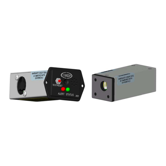
- Page 1 CO Guardian LLC Document: 353-002 1951 E. AIRPORT DRIVE Date: 11/15/05 TUCSON, AZ. 85706 REV ORIG. OWNERS MANUAL CARBON MONOXIDE DETECTOR MODELS Panel mount and Remote Detectors (R) 353 and 353R) 353 FAMILY MODEL OWNERS/INSTALLATION MANUAL Page 1 of 22...
-
Page 2: Description
CO Guardian LLC Document: 353-002 1951 E. AIRPORT DRIVE Date: 11/15/05 TUCSON, AZ. 85706 REV ORIG. LOG OF REVISIONS PAGE DATE DESCRIPTION APPROVED 1 thru 18 11/15/05 Initial Release ASH VIJ 353 FAMILY MODEL OWNERS/INSTALLATION MANUAL Page 2 of 22... -
Page 3: Table Of Contents
Forward 1.0 General 2.0 Physical Descriptio 3.0 Leading Particulars 4.0 Scope 5.0 Service Facilities 6.0 Installation 353 Panel Mount 6.1 Installation 353R Remote Mount 6.2 Recommended Installation Areas 6.2.1 DB9 pinout Diagram 6.2.2 Installation Check 353 6.2.3 Installation Check 353R 7.0 Maintenance... -
Page 4: Forward
Send your comments to the address above. This unit is designed to be installed in Experimental Aircraft. If this unit is installed in a certified aircraft, appropriate FAA approval is required prior to installation. 353 FAMILY MODEL OWNERS/INSTALLATION MANUAL Page 4 of 17... -
Page 5: General
Detector TABLE 1 - Part Numbers The Detector must be returned to CO Guardian at the end of Service Life for replacement and calibration of the CO sensor to maintain airworthiness of the unit. NOTE: The main reason for replacement of the sensor is the degradation of the sensor and dirt accumulation over the years. -
Page 6: Leading Particulars
-20 °C Temperature Variation Altitude 25,000’ for 353P and 353PR Humidity POWER REQUIREMENTS Power – 14/28 VDC Models Nominal 9.0 vdc to 30.3vdc Dissipation (maximum) <1 watt TABLE 2 - Leading Particulars 353 FAMILY MODEL OWNERS/INSTALLATION MANUAL Page 6 of 17... -
Page 7: Scope
CO levels. The 353 and 353R have a built in pressure compensation sensor to detect cabin altitude changes up to 25,000 to give a better accuracy in CO Detection. These models also alarm if the cabin altitude goes above 10,000 feet for 10 seconds, 12,500 for 10 seconds and stays on over 14,000 feet. -
Page 8: Service Facilities
REV ORIG. SERVICE FACILITIES (all models) The operator can service all other components of the installation at an FAA certified Repair Station or by A&P mechanic. CO Detectors must me returned to CO Guardian for repair calibration or overhaul. NOTE The sensor requires special gases for testing. -
Page 9: Installation 353R Remote Mount
The panel mount unit can be installed anywhere around the instrument panel within pilots reach. Verify that there is no obstruction of airflow to the unit. INSTALLATION 353R using drawing (353-001 Rev. Orig or later) Installation 353R using drawing 353-001 Rev. Orig or later a. -
Page 10: Recommended Installation Areas
• Typical installation areas are depicted below in Figurers 1, 2, 3, and 4. Detectors locations Remote or panel mount FIGURE 1 - TYPICAL RIGHT HAND INSTRUMENT PANEL SHOWN Test/Reset Button Amber Alert Annunciator 2 AMP CIRCUIT FIGURE 2 - TYPICAL PILOT INSTALLATION SHOWN 353 FAMILY MODEL OWNERS/INSTALLATION MANUAL Page 10 of 17... -
Page 11: Db9 Pinout Diagram
CO Detector weight is 4.0 oz. 6.2.3 INSTALLATION CHECKS 353R a. With the CO Detector disconnected from the aircraft harness, conduct a continuity check of the added aircraft wiring. 353 FAMILY MODEL OWNERS/INSTALLATION MANUAL Page 11 of 17... -
Page 12: Maintenance
WARNING: If all Models show a flashing remote Amber light every 4 seconds, return the unit to CO Guardian for repair or replacement. MFG Manual if Remote light is displayed on the MFD. Field repair or service is allowable on all of the installed system components except for the CO Detector Indicator itself. -
Page 13: Scheduled Maintenance
NO FIELD SERVICE OR OVERHAUL OF MODELS IS AUTHORIZED. WEIGHT AND BALANCE / EQUIPMENT LIST (ALL MODELS) The Aero 353’s CO Detector installation weighs 0.125 lbs. Reference the aircraft weight and balance manual for moment arm. 353 FAMILY MODEL OWNERS/INSTALLATION MANUAL... -
Page 14: Limitation
TUCSON, AZ. 85706 REV ORIG. 10.0 LIMITATIONS (ALL MODELS) The 353 family of Detectors may not replace any existing instrument or indicator required by the type design or operating limits. 11.0 NORMAL PROCEDURES 353 When the airplane master battery switch is selected ON, the Remote CO Detector goes through a self-test routine. -
Page 15: Emergency Procedures
Manufacturers MFD. DO not recycle the unit through the circuit breaker. A three-minute delay is required for the CO sensor to stabilize after each power-up in the -001 through -004 P/N units. 353 FAMILY MODEL OWNERS/INSTALLATION MANUAL Page 15 of 17... -
Page 16: Unit Failure Indication
RS-232 input capability. See Multi-Function display manufacturers Installation Manual for interface guidance. The CO ALERT can be reset through the RS-232 interface provided the Multi-Function system contains the reset capability. 353 FAMILY MODEL OWNERS/INSTALLATION MANUAL Page 16 of 17... -
Page 17: Warranty
During the above warranty period, your product will be replaced with a comparable product if the defective product is returned, postage prepaid, to CO Guardian, Customer Service Department, 1951 East Airport Drive, Tucson, AZ 85706, together with proof of purchase date.
Need help?
Do you have a question about the 353 and is the answer not in the manual?
Questions and answers