
Related Manuals for V-GREAT VG-6132

Summary of Contents for V-GREAT VG-6132
- Page 1 VG-6132 Gas Extinguishing Panel Installation and Operation Manual (Ver 1.02, October 2019) V-GREAT GLOBAL CORPORATION...
-
Page 2: Table Of Contents
VG-6132 Gas Extinguishing Panel CONTENTS Chapter 1 Overview ............................1 Chapter 2 Technical Specifications ......................1 2.1 Functions ..............................1 2.2 Technical Specifications........................... 1 Chapter 3 Structure ............................1 3.1 Appearance and structure dimension ....................1 3.2 Installation Dimension..........................2 3.3 Front Panel ............................... -
Page 3: Chapter 1 Overview
VG-6132 Gas Extinguishing Panel Chapter 1 Overview VG-6132 Gas Extinguishing Panel(called the panel or control panel for short)is a kind of extinguishant gas releasing equipment of low cost and high efficiency Use the graphic dot matrix as liquid crystal display (LCD). -
Page 4: Installation Dimension
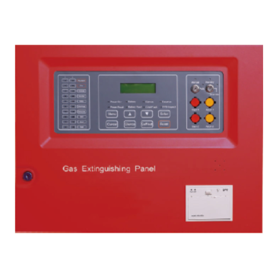
330mm VG-6132 Gas Extinguishing Panel Fig. 3-1 3.2 Installation Dimension Mounting hole of VG-6132 Gas Extinguishing Panel is shown in Fig. 3-2 ( 360mm*135mm ) . Two Mounting Holes Fig. 3-2 3.3 Front Panel Front panel of VG-6132 Gas Extinguishing Panel is shown in Fig. 3-3. - Page 5 VG-6132 Gas Extinguishing Panel Fig. 3-3 Critical status of VG-6132 Gas Extinguishing Panel are indicated by LEDs, description is shown as below. Main control section ◇ Power(Green) :It turns on when the main power is supplied and turns off when the power is low voltage or the power cable is broken.
-
Page 6: Internal Structure
VG-6132 Gas Extinguishing Panel ◇ Fault ( Amber) : It turns on whenthere is open or short occurred in the output circuits, and turns off when the circuit is back to normal. 3.4 Internal Structure 3.5 Terminals Description 3.5.1. Wiring description of terminal 1 is shown below. -
Page 7: Chapter 4 Installation And Commissioning
VG-6132 Gas Extinguishing Panel 3.5.2. Wiring description of terminal 2 is shown below. COM Fire COM Fault COM Response COM Start 1 2 3 4 5 6 7 8 Notes: 1. COM Fire, COM Start and COM Response are normally closed, and open when activated. -
Page 8: Wiring
VG-6132 Gas Extinguishing Panel Enter into the standby state, check the power fault and operating keys, as well as field devices are in good condition. 4.5 Wiring After checking the control panel, if the results of all the tests meet the requirements, please refer to Chapter 3 Structure in this manual for connecting terminals with field devices. -
Page 9: System Operation
VG-6132 Gas Extinguishing Panel Fig. 5-2 Pressing “Enter ” key, the cursor can move up and down to set delay time. Pressing “▼” key, delay time will be added 1. Pressing “Enter” key saves the delay time. Then pressing “Cancel” key returns to the loop check. -
Page 10: Self-Test
VG-6132 Gas Extinguishing Panel The First Line indicates the system time. The Second Linethat there is fire alarm message in Zone 2. 5.3 Self-test Pressing “Self-test” key,and then “Enter” key four times, the system begins self-testing. All LEDs of the system are lit, the buzzer gives continuous alarm sound and LCD display “self-testing…”. -
Page 11: Chapter 6 Commissioning
VG-6132 Gas Extinguishing Panel Chapter 6 Commissioning 6.1 Commissioning notes 1. Before commissioning works, please take off the wires, and use the Multimeter to test the resistance value of cables at first. The resistance of all wires should be over 4.7 kΩ. -
Page 12: Chapter 7 Trouble Shooting
VG-6132 Gas Extinguishing Panel Pic6-2 Chapter 7 Trouble Shooting Trouble shooting is shown in Table 8-1. Table 8-1 Problem Reason Solution Circuit fault 1. Polarity reversed incorrect 1.Correct the connection. connection. 2.Replace the fault end of line resistor. 2. End of line resistor is fault. -
Page 13: Chapter 8 Cautions
VG-6132 Gas Extinguishing Panel Chapter 8 Cautions This product belongs to precise electronics, it should be kept by a special person, others are not allowed to touch it at random. Customers should record the information on duty. If there is an alarm, first press Silence key on the control panel, confirm the fire and take proper procedures immediately.
Need help?
Do you have a question about the VG-6132 and is the answer not in the manual?
Questions and answers