Table of Contents
Advertisement
Quick Links
Advertisement
Table of Contents

Related Manuals for Matthews Fan Company ATLAS FAN COMPANY Donaire


Summary of Contents for Matthews Fan Company ATLAS FAN COMPANY Donaire
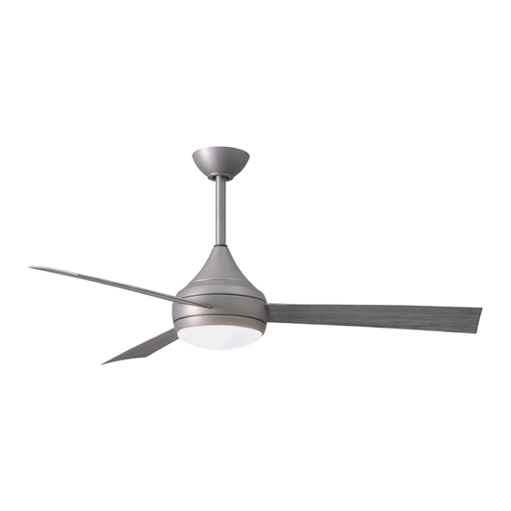
- Page 1 Donaire 52” CEILING FAN READ AND SAVE THESE INSTRUCTIONS YG480-MG FAN RATING AC 220-240V~, 50/60Hz Please do not use any electric or battery powered tools in the assembly and installation of this or any Matthews Fan Company product. AUSTRALIA ONLY...
-
Page 2: Table Of Contents
TABLE OF CONTENTS Tools and Materials Required..................Package Contents ......................Safety Rules........................Mounting Options......................Attaching the Fan Blades....................Hanging the Fan ......................Make the Electric Connections..................Finishing the Installation....................Attaching the Fan Blades....................Installing the Light Kit..................... Operating the Remote Control..................Operating Your Fan ..................... -
Page 3: Tools And Materials Required
(2), washers (2), star washers (2), wire nuts (3) 2) Blade attachment hardware: screws with lock washers (10) Please do not use any electric or battery powered tools in the assembly and installation of this or any Matthews Fan Company product. -
Page 4: Safety Rules
READ AND SAVE THESE SAFETY AND INSTALLATION INSTRUCTIONS. Consult a licensed electrician if unsure of any point below mentioned. DANGER/WARNING/CAUTION 1. High voltage and moving parts around motors and motor driven equipment can cause serious or fatal injuries. Always disconnect power source at main switch before wiring, servicing or cleaning unit. -
Page 5: Mounting Options
13. Warning: To reduce the risk of fire, electrical shock or personal injury, mount to outlet box marked acceptable for fan support and use screws provided with outlet box. 14. WARNING: This product is designed to use only those parts supplied with this product and/or accessories designated specifically for use with this product. -
Page 6: Attaching The Fan Blades
5. HANGING THE FAN Ceiling hanger Before touching a screw driver thoroughly read bracket these instructions. Ceiling Warning/Caution: Before installing fan, turn off canopy power at service panel and check all visible screws and bolts for tightness. Canopy cover 1. Remove the decorative canopy bottom cover Figure 1 from the canopy by turning the cover counter clockwise. -
Page 7: Make The Electric Connections
9. Now lift the motor assembly into position and place the hanger ball into the hanger bracket. Rotate down rod until the "Check Tab" has dropped into the "Registration Slot" and the Screw down rod and ball assembly seat firmly. The down rod and ball assembly should not rotate if this is done correctly. - Page 8 5. Be sure to connect the male plug (from receiver) and female plug (from terminal block) Black (”LI” to fan) together. (Fig. 10 &11) Blue (LI) Brown (”L” to fan) Receiver 6. Be sure to snap together the male and Blue Black (L) female plugs.
-
Page 9: Finishing The Installation
7. FINISHING THE INSTALLATION Outlet box 1. Tuck connections neatly into ceiling outlet box. Hanger bracket 2. Slide the canopy up to hanger bracket and Screws place the key hole on the canopy over the screw on the hanger bracket, turn canopy until it locks in place at the narrow section of Canopy the key holes. -
Page 10: Installing The Light Kit
9. ATTACHING THE MOUNTING PLATE Step 1. Remove the 1 of 3 screws from the mounting ring and keep it for future use. Loosen the other 2 screws. (Do not remove) Step 2. Place the key holes on the mounting plate over the 2 screws previously loosened from the mounting ring, turn mounting plate until it locks in place at the narrow section of the key holes. -
Page 11: Operating The Remote Control
11. OPERATING THE Light dimmer function REMOTE CONTROL select switch LEARN MODE PROCESS 1. Control and receiver have been factory ON/OFF programmed. If replacing the transmitter or DIMMER receiver, the learn mode process will need to be used. (Fig. 16) Learning button 2. -
Page 12: Operating Your Fan
12. OPERATING YOUR Speed settings for warm or cool weather depend on factors such as the room size. Ceiling height, number of fans and so on. NOTE: To operate the reverse function on this fan, press the reverse button while the fan is running. -
Page 13: Care Of Your Fan
13. CARE OF YOUR FAN Here are some suggestions to help you maintain your fan 1. Because of the fan's natural movement, some connections may become loose. Check the support connections, brackets, and blade attachments twice a year. Make sure they are secure. (It is not necessary to remove fan from ceiling.) 2.
Need help?
Do you have a question about the ATLAS FAN COMPANY Donaire and is the answer not in the manual?
Questions and answers