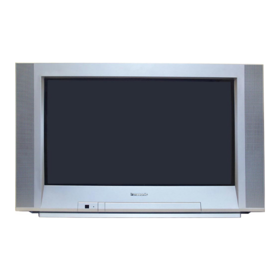
Panasonic TX-32DK1L Service Manual
Euro-4 chassis
Hide thumbs
Also See for TX-32DK1L:
- Operating instructions manual (40 pages) ,
- Service manual (14 pages)
Table of Contents
Advertisement
Quick Links
SPECIFICATIONS
Power Source:
220-240V a.c., 50Hz
Power Consumption:
95W
Stand-by Power
Consumption:
1.4W
Aerial Impedance:
75Ω unbalanced, Coaxial Type
Receiving System:
PAL I, PAL-525/60
M.NTSC
NTSC (AV only)
Receiving Channels:
UHF E21-E69
VHF A1-S20
Intermediate Frequency:
Video/Audio
Video
39.5MHz
Audio
33.5MHz
32.95MHz (NICAM)
Colour
35.07MHz
Terminals:
AUDIO MONITOR OUT Audio (RCAX2)
AV1 IN
Video (21 pin)
Audio (21 pin)
RGB (21 pin)
AV1 OUT
Video (21 pin)
Audio (21 pin)
AV2 IN
Video (21 pin)
Audio (21 pin)
S-Video IN
(21-pin)
AV2 OUT
AV3 IN
High Voltage:
Picture Tube:
Audio Output:
(Music Power)
Headphones:
Accessories
supplied:
500mV 1kΩ
Dimensions:
Height:
1V p-p 75Ω
Width:
500mV rms 10kΩ
Depth:
Net weight:
1V p-p 75Ω
500mV rms 1kΩ
Specifications are subject to change without notice.
Weights and dimensions shown are approximate.
1V p-p 75Ω
NOTE: This Service Manual should be used in conjunction with
500mV rms 10kΩ
the EURO-4 Technical guide.
Y: 1V p-p 75Ω
C: 0.3V p-p 75Ω
ORDER No. SM-99095
Colour Television
TX-32DK1L
EURO-4 Chassis
Video (21 pin)
1V p-p 75Ω
Audio (21 pin)
500mV rms 1kΩ
Selectable output (21 pin)
S-Video IN
Y: 1V p-p 75Ω
(4-pin)
C: 0.3V p-p 75Ω
Audio (RCAx2)
500mV rms 10kΩ
Video (RCAx1)
1V p-p 75Ω
30.5kV ± 1kV
W76ESF031X13 76cm
Front Left/Right
2 x 15W
8Ω Impedance
3.5mm
Remote Control
2 x R6 (UM3) Batteries
VS-DK1/2 Video Cabinet
561mm
896mm
558.5mm
46.5kg
Advertisement
Table of Contents

Subscribe to Our Youtube Channel
Summary of Contents for Panasonic TX-32DK1L
- Page 1 ORDER No. SM-99095 Colour Television TX-32DK1L EURO-4 Chassis SPECIFICATIONS Power Source: 220-240V a.c., 50Hz AV2 OUT Video (21 pin) 1V p-p 75Ω Power Consumption: Audio (21 pin) 500mV rms 1kΩ Selectable output (21 pin) Stand-by Power AV3 IN S-Video IN Y: 1V p-p 75Ω...
-
Page 2: How To Move The Chassis Into Service Position
HOW TO MOVE THE CHASSIS INTO SERVICE POSITION 1. Remove the bead clamper from the mains lead and affix, using back cover screw, into top right-hand cabinet rib (A), shown in Fig. 4. 2. Hold and lift the rear of the chassis and gently pull the chassis toward you, as shown in Fig. -
Page 3: Adjustment Procedure
ADJUSTMENT PROCEDURE Item / Preparation Adjustments +B SET-UP Set the +B voltage up as follows:- Adjust R811 so that B2 shows 148V ± 1V. Receive a Greyscale signal. Confirm the following voltages. Set the controls :- ± 0.25V ± 0.25V ±... -
Page 4: Waveform Pattern Table
WAVEFORM PATTERN TABLE Vert Drive VFLB Vert Out IC451 Pin 2 IC451 Pin 3 IC601 Pin 31 20ms 20ms 20ms H - Out H - Out H - Pulse IC601 Pin 50 IC701 Pin 5 Base Q503 64µs 64µs 64µs HFLB HFLB Video Out... -
Page 5: Video Block Diagram
VIDEO BLOCK DIAGRAM Y - BOARD E - BOARD Q906 Q908 COILS Q905 Q907 Q909 IC601 61 V IN 1 Q950 Q951 TUNER Q104 IC351 SVM OUT 34 VIDEO PROCESSOR B OUT 39 Q353 Q305 Q306 43 B IN Q105 OUTPUT 42 G IN G OUT 38... -
Page 6: Audio Block Diagram
AUDIO BLOCK DIAGRAM M - BOARD E - BOARD IC2101 E16A AUDIO IC251 PROCESSOR AUDIO Q252 DACM_R 24 TUNER Q2102 OUTPUT DACM_L 25 Q2103 L 11 Q251 HEADPHONE Q103 SC3_IN_L 37 44 MONO IN SC3_IN_R 38 X102 Q101 49 ANA_IN2+ 1 R OUT SC1_OUT_R 30 Q102... -
Page 7: Control Block Diagram
CONTROL BLOCK DIAGRAM H - BOARD E - BOARD TUNER IC3401 L/L’ POS/NEG VIDEO IC2101 SWITCHING AUDIO IC601 SDA 1 PROCESSOR VIDEO PROCESSOR SCL 1 SERVICE / TEST SDA 1 SCL 1 SDA 2 SCL 2 VPROT Q451 KEYSCAN IC1101 IC1103 SCL 2 MICRO... -
Page 8: Power Supply Block Diagram
POWER SUPPLY BLOCK DIAGRAM E - BOARD M - BOARD 5V SBY Q852 E16A D867 IC1061 Q855 REMOTE D868 CONTROL Q853 Q854 RECEIVER IC251 AUDIO D862 T802 RL801 R854 OUTPUT T801 D801 Line Filter 150V 150V D850 Line Y - BOARD Filter R802 Q850...


Need help?
Do you have a question about the TX-32DK1L and is the answer not in the manual?
Questions and answers