Table of Contents
Advertisement
Quick Links
Advertisement
Table of Contents

Related Manuals for Delta-T Devices PR2


Summary of Contents for Delta-T Devices PR2
- Page 1 User Manual for the Profile Probe type PR2-UM-3.0 Delta-T Devices Ltd...
- Page 2 Delta-T Devices Ltd. Under the law, copying includes translation into another language. Copyright © 2004, Delta-T Devices Ltd. Patent pending The Profile Probe has been developed by Delta-T Devices and uses novel measurement techniques, patent pending. CE conformity The Profile Probe type PR2 conforms to EC regulations...
-
Page 3: Table Of Contents
Contents Introduction Description Parts list Care and safety instructions Routine maintenance PR2 Cleaning and Chemical Avoidance Instructions How the Profile Probe works Operation Preparation for reading Insert the Profile Probe Portable monitoring Record readings with a data logger Calibration Conversion to soil moisture... -
Page 4: Introduction
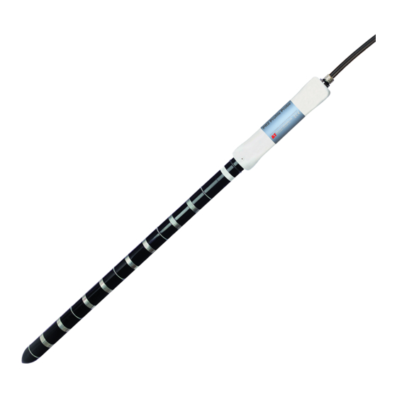
Introduction Description The Profile Probe measures soil moisture content at different depths within the soil profile. It consists of a sealed polycarbonate rod, ~25mm diameter, with electronic sensors (seen as pairs of stainless steel rings) arranged at fixed intervals along its length. When taking a reading, the probe is inserted into an access tube. - Page 5 PR2/6 and PR2/4 in soil Sensor 1 Pair of sensor rings 1 metre Electromagnetic fields extend into the soil and detect soil moisture Profile Probe User Manual 3.0a Introduction...
-
Page 6: Parts List
Your consignment may have the following parts: Part Sales Code Description Profile Probe PR2/4 PR2/4 with 4 sensors (as shown) or PR2/6 with 6 sensors. Both supplied in PR2/6 protective tube, with spare o- rings and centring springs Access tube spacer... -
Page 7: Care And Safety Instructions
Don’t lay the PR2 in a puddle because water may creep under the rings – if you suspect this has happened warm gently (< 50°C) for 24 hours. -
Page 8: Pr2 Cleaning And Chemical Avoidance Instructions
PR2 Cleaning and Chemical Avoidance Instructions The PR2 shaft is made of polycarbonate plastic which is an exceptionally strong material, and it can withstand bending forces far in excess of anything likely to be encountered in practice. However, polycarbonate can develop stress cracking when exposed to certain chemicals. -
Page 9: How The Profile Probe Works
How the Profile Probe works Before you rush out and hammer your access tubes into the soil, it will help to understand a little about how the Profile Probe works: When power is applied to the Profile Probe..it creates a 100MHz signal (similar to FM radio). -
Page 10: Operation
The Profile Probe must be used within an access tube. The process of augering holes and installing access tubes is described in the Augering Manual. Equipment You may require the following equipment for a site visit: PR2 in protective tube Access tube spacer Spare collars caps... -
Page 11: Insert The Profile Probe
Ensure that the Profile Probe is pushed all the way down over the top o-ring. The PR2 is then fully sealed in its access tube and ready either for immediate reading or for attaching to a logger for extended monitoring. -
Page 12: Portable Monitoring
Press Store to save or Esc to discard the reading. If you want to maximise the sampling volume, take 2 further readings with the probe rotated through 120° each time. Remove the PR2, replace the access tube cap and move on to a new site…. Viewing stored readings If you have saved data, connect the HH2 to your PC and run HH2Read to retrieve the readings. -
Page 13: Record Readings With A Data Logger
Pocket PC with Pocket DeltaLINK. Connect the Profile Probe The PR2 can be connected directly to the DL6 with the supplied cable. Extension cables can be added as required up to 100m. Configure the DL6... - Page 14 When used with a DL2e this should be connected using the PRC/w-05 cable, which provides the following connections. Cable Function Notes Colour Power V+ 5-15V DC, PR2/4 80mA, PR2/6 120 mA. Power 0V is cable screen. Black Power 0V Green Signal COM Common signal output...
- Page 15 The DL2e has two warm-up relay-controlled outputs. Each relay can typically power up to 12 PR2/4 or 8 PR2/6 Profile Probes. Note: For best economy the Profile Probe should be powered up using a 1 second warm-up time.
- Page 16 Other data loggers The connections and power requirements will usually be the same as for the DL2e. If you simply want to log the sensor voltages directly, they can be treated as differential voltage sources of range 0 – 1.1 V DC, and the data logger should be configured accordingly.
-
Page 17: Calibration
As a result, the performance of the Profile Probe is best understood if it is split into these two stages: calibration: soil moisture (θ) determines √ε Soil response: √ε determines PR2 output (Volts) Profile Probe Soil calibration Soil calibration Slope (... - Page 18 Generalised calibrations Most soils can be characterised simply by choosing one of the two generalised calibrations we supply, one for mineral soils (predominantly sand, silt or clay) and one for organic soils (with a very high organic matter content). Mineral soils Organic soils These values have been used to generate the slope and offset conversions and linearisation tables in the Conversion to soil...
-
Page 19: Conversion To Soil Moisture
Profile Probe response All Profile Probes have the same dielectric performance: Profile Probe output PR2 readings fitted curve PR2 output (Volts) This relationship can be fitted very precisely up to ~ 0.5 m by the following polynomial: ε − −... - Page 20 Polynomial conversion Combining the Soil calibration Profile Probe response steps, the conversion equation becomes: − − − − . 1 [ θ where are the calibration coefficients above. For a generalised mineral soil this becomes: θ − − − − And for an organic soil: θ...
- Page 21 mineral organic soil moisture soil soil Volt Volt %vol 0.257 0.177 0.05 0.379 0.280 0.10 0.497 0.394 0.15 0.595 0.501 0.20 0.677 0.590 0.25 0.749 0.667 0.30 0.810 0.734 0.35 0.860 0.793 0.40 0.899 0.843 0.45 0.930 0.882 0.50 0.956 0.914 0.55 0.977...
-
Page 22: Reading Accuracy
The Profile Probe is accurate and reliable. However this doesn’t guarantee that the readings you take with a PR2 are an accurate measure of the soil moisture. There are three particular sources of error that you need to consider when measuring soil moisture with the Profile Probe: ♦... - Page 23 Salinity Changes in soil salinity cause a change in reading, which will appear as a change in soil moisture. Typical effects on Profile Probe readings are an apparent change of < 0.005 m soil moisture for a change of 100 mS.m soil salinity.
-
Page 24: Troubleshooting
Air reading Keep the PR2 in its protection tube and hold it away from any other objects. Take a reading using an HH2 meter, or other meter or logger. The reading should be 75 ±20mV. - Page 25 Water reading Insert the PR2 fully into an access tube and immerse the tube into a large body of water at 20 to 25°C. The water container should be sufficiently large so that the PR2 is >100mm from any edge. Take a reading using an HH2 meter, or other meter or logger.
-
Page 26: Technical Reference
Minimum: 5.5V DC with 2m cable, 7.0V with 100m.* Maximum: 15V DC Power requirement PR2/4 consumption: < 80 mA PR2/6 consumption: < 120 mA 4 (PR2/4) or 6 (PR2/6) analogue voltage outputs: (mineral Outputs ~0 to 1.0V DC corresponding to 0 - 0.6 m calibration) Cable 8-core screened. -
Page 27: Performance
The Profile Probe output has been tested as follows: PR2 conductivity response 60.0 50.0 40.0 30.0 20.0 PR2 in wet soil ideal response in wet soil 10.0 PR2 in damp soil ideal response in damp soil Pore Water Conductivity (mS.m-1) Profile Probe User Manual 3.0a... - Page 28 Temperature The Profile Probe has a very low intrinsic sensitivity to changes in temperature, as in this example: PR2 output versus temperature Temperature (°C) This relationship is dependent on soil composition (particularly clay content) and the soil moisture level, see ref. [7].
-
Page 29: Definitions
Definitions Volumetric Soil Moisture Content is defined as where V is the volume of water contained in θ the sample and V is the total volume of the soil sample. The preferred units for this ratio are m , though %vol is frequently used. - Page 30 Salinity The preferred SI units for ionic conductivity are mS.m (where S is Siemens, the unit of electric conductance = ohm The following conversions apply: = 0.01 dS.m 1 mS.m = 0.01 mS.cm = 0.01 mmho.cm = 10 µS.cm Soil salinity is also partitioned into the following descriptive categories: non-saline 0 - 200...
-
Page 31: References
References Gaskin, G.J. and J.D. Miller, 1996 Measurement of soil water content using a simplified impedance measuring technique. J. Agr. Engng Res 63, 153-160 Topp, G.C., J. L. Davis and A. P Annan 1980 Electromagnetic determination of soil water content. Water Resour. -
Page 32: Technical Support
Technical Support Terms and Conditions of Sale Our Conditions of Sale (ref: COND: 1/07) set out Delta-T's legal obligations on these matters. The following paragraphs summarise Delta T's position but reference should always be made to the exact terms of our Conditions of Sale, which will prevail over the following explanation. - Page 33 In your enquiry, always quote instrument serial numbers, software version numbers, and the approximate date and source of purchase where these are relevant.. Contact details: Tech Support Team Delta-T Devices Ltd 130 Low Road, Burwell, Cambridge CB25 0EJ, U.K. email: tech.support@delta-t.co.uk email: repairs@delta-t.co.uk...
-
Page 34: Soil-Specific Calibration
Appendix A Soil-specific calibration This note provides details of 3 techniques for generating soil-specific calibrations: Laboratory calibration for substrates* and non-clay soils Laboratory calibration for clay soils Field calibration We use the term substrate to refer to any artificial growing medium. Underlying principle Soil moisture content (θ) is proportional to the refractive index... -
Page 35: Laboratory Calibration Non-Clay Soils
Appendix A Laboratory calibration non-clay soils This is the easiest technique, but it’s not suitable for soils that shrink or become very hard when dry. Equipment you will need: ThetaProbe and meter Soil corer (if doing a calibration for a cohesive soil rather than sand or a substrate) Heat-resistant beaker (≥... - Page 36 Appendix A Insert ThetaProbe into the sample and record its output in Volts. = 0.672V Dry the sample thoroughly. With mineral soils this is usually achieved by keeping it in the oven at 105°C for several hours or days (the time required depends on the sample size and porosity).
-
Page 37: Laboratory Calibration For Clay Soils
Appendix A drying, (W – W ) and its volume, L θ − − θ = 0.25 Calculate In the wet soil V = V = 0.672 Volts and substituting ε gives Finally ε ε θ θ − − − −... - Page 38 Appendix A Weigh the wet sample, including the beaker. = 743.3g Insert ThetaProbe into the wet sample and record its output in Volts. = 0.672V Dry the sample until still moist, ~15% water content. Gentle warming can be used to accelerate the process, but take care not to over-dry in places, and allow time for the water content to equilibrate throughout the sample...
- Page 39 Appendix A Dry the sample thoroughly. With mineral soils this is usually achieved by keeping it in the oven at 105°C for several hours or days (the time required depends on the sample size and porosity). Weigh the dry sample in the beaker. = 627.2g Substituting in the ML2 equation Calculations...
-
Page 40: Field Calibration
Appendix A Field calibration Field calibration is the surest method of calibration. We strongly recommend it for Profile Probe installations featuring high water content (usually high-clay-content) and high conductivity, as it is the only technique likely to give good results. However it is typically far more time consuming and requires access to considerably more equipment than laboratory calibration. - Page 41 Appendix A Notes and example Process Take Profile Probe readings (as voltages) over a period of time as the soil moisture content changes. Ideally this would include 3 or more distinct soil moisture levels covering a change > 0.1m At the same time, take several independent soil moisture readings spaced around the Profile Probe access tube.
- Page 42 Appendix A Variable Intercept Fit a linear trendline to the data, and in the Options tab choose to display the equation. You may need to adjust the number format for the equation to 3 decimal places. The calibration coefficients can then be read off directly.
-
Page 43: Index
Index Access tube, 4, 6, 7, 9, 10, 11, Installation, 4, 10, 15, 18, 22 12, 20, 22, 26, 28, 31, 40, bung, 6 Moisture content, 4, 9, 19, 22, cap, 6, 7, 11, 12 26, 31, 34, 40, 41 Accuracy, 22, 26 Air gaps, 9, 22 Power supply, 9, 14, 15, 16, 26...
Need help?
Do you have a question about the PR2 and is the answer not in the manual?
Questions and answers