Advertisement
SILENT
KNIGHT
®
RA-100 Remote Annunciator
Installation
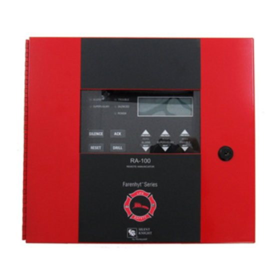
The optional Model RA-100 Remote Annunciator, shown in
Figure 1, performs the same functions as the on-board
annunciator. Operation is identical. The RA-100 can be surface
or flush monted.
Up to 8 RA-100s can be added to the IFP-100 system.
Figure 1: Model RA-100 Remote Annunciator
RA-100 installation involves the following steps:
1.
Make sure power is off at the panel.
2.
Mount the RA-100 in the desired location (see Section
"Mounting the RA-100" ).
3.
Connect the RA-100 to the panel (see Figure 2).
4.
Use the dipswitches on the back of the RA-100 to assign an
ID# to the RA-100 (see Section 4.10.1 of Manual P/N
151280).
5.
The new RA-100 module must be added to the system
through programming. JumpStart will add the module
automatically (refer to Manual P/N 151280). You can also
add it manually. Select a name, if desired (see Section 7 of
manual 151280).
Wiring Connections
Wire the RA-100 to the FACP as Shown in Figure 2.
Figure 2: SBUS Connections
Supervised
Power Limited
Specifications
Parameter
Operating Voltage:
24 VDC
Standby:
20 mA
Current
Alarm:
65 mA
Operating Temperature: 0° to 49° C (32° to 120° F)
Flush
Overall: 12-1/4" W x 11.5" H x 7/8" D
Mount:
31.1 cm W x 29.2 cm H x 2.2 cm D
See "Flush Mounting" for back box
dimensions.
Dimensions:
Surface
Including trim ring:
Mount:
12-1/4" W x 11.5" H x 3" D
31.1 cm W x 29.2 cm H x 7.6 cm D
Mounting the RA-100
This section of the manual describes mounting the remote
annunciator. The annunciator can be flush- or surface-mounted.
Flush Mounting
This section of the manual describes flush mounting.
Follow these steps to flush mount the RA-100
1.
The back box dimensions are 9-3/8" w x 8-3/8" h. The
minimum depth 2". The back box can be mounted prior to
the complete installation of the RA-100 using any of the
mounting holes shown in Figure 3.
Mounting Holes
Mounting Holes
Figure 3: Back Box Mounting Holes
Value
P/N 151283
Advertisement
Table of Contents

Related Manuals for SILENT KNIGHT RA-100


Summary of Contents for SILENT KNIGHT RA-100
- Page 1 Mounting Holes “Mounting the RA-100” ). Connect the RA-100 to the panel (see Figure 2). Use the dipswitches on the back of the RA-100 to assign an ID# to the RA-100 (see Section 4.10.1 of Manual P/N 151280). The new RA-100 module must be added to the system through programming.
- Page 2 Do not tighten all the way. See Figure 6. Place a level on top of the back box, with the back 7550 Meridian Circle Maple Grove, MN 55369-4927 763-493-6455 800-328-0103 Fax: 763-493-6475 http://www.silentknight.com © 2001 Silent Knight P/N 151283, 10/01 P/N 151283...
Need help?
Do you have a question about the RA-100 and is the answer not in the manual?
Questions and answers