
Related Manuals for agrifac ENDURANCE

Summary of Contents for agrifac ENDURANCE
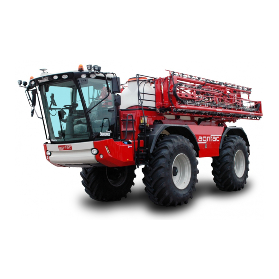
- Page 1 Publ. 20201102 ENDURANCE CROP SPRAYER CONDOR ENDURANCE 2 (CE02) - 2018–2020 USER MANUAL READ AND UNDERSTAND THIS MANUAL BEFORE USING THE MACHINE...
- Page 2 Internet www.agrifac.com Copyright © No part of this manual may be reproduced or made public without the written permission of Agrifac Machinery B.V. Changes This manual is subject to change without notice. Contact your dealer or go to www.agrifac.com for the latest publication.
- Page 3 Dealer Fill in the details of your dealer. Name Address ℡ Telephone E-mail Machine identification Fill in the identification details of the machine. You can find these details on the identification plate. Also, fill in the delivery date. Type Serial number Year of manufacture : Delivery date...
- Page 4 Only technically trained persons who have read and understood this manual may operate and maintain the sprayer. Technical training courses are organized by the Agrifac Academy. To protect the environment, in most countries plant protection products may only be applied by persons with a valid certificate of competence (a spraying certificate).
- Page 5 About this manual This manual describes the operation and maintenance of the sprayer. Supplied documentation • This manual. • The manual of the radio. • The manual of the engine. • The manual of the observation system (option). • The manual of the foam marker (option). •...
- Page 6 Contact your dealer: • In case of problems. Your dealer will help you as soon as possible. • For a service contract. With a service contract the machine is maintained by qualified per- sonnel and with genuine Agrifac parts. Endurance2-UM-2018-20-R0-en-2020420...
- Page 7 Spare parts parts Contact your dealer for spare parts (or go to www.agrifac.com). Use genuine Agrifac parts. Non-genuine parts can damage the machine and make it unsafe. Agrifac is not liable for damage or injury caused by non-genuine parts. Warranty You are entitled to a warranty if, despite correct operation and proper maintenance, a defect oc- curs.
- Page 8 Endurance2-UM-2018-20-R0-en-2020420...
-
Page 9: Table Of Contents
TABLE OF CONTENTS SAFETY ........................13 Introduction ......................13 Symbols ........................ 13 Emergency stop ....................13 Emergency exit ..................... 14 Emergency hammer ....................14 First-aid kit and fire extinguisher ................14 Safety labels......................15 Information labels ....................23 DESCRIPTION ....................... 27 Introduction ...................... - Page 10 4.11 Start-up after winter storage ..................49 OPERATION ......................51 Introduction ......................51 Driving safely on the road ..................51 Spraying safely on the field ...................52 Fuelling .........................54 Driver’s seat, armrest and steering column ............56 Control panels in the cab roof ................59 5.6.1 Pressurized cab (option) ...............61 Air conditioning ......................63 Steering column switches ..................64...
- Page 11 6.14 Batteries ......................106 6.15 Air conditioning ....................106 6.16 Seat belts ......................107 6.17 Handwash tank ....................107 6.18 Windscreen washer fluid ..................108 6.19 Windscreen wiper ....................108 6.20 AdBlue filters ....................... 109 6.21 Cooling unit ......................111 6.22 Coolant ........................
- Page 12 SPECIFICATIONS ....................153 10.1 Introduction ......................153 10.2 Dimensions and weights ..................153 10.3 Speeds ........................ 153 10.4 Electrical specifications ..................153 10.5 Undercarriage ..................... 154 10.6 Diesel engine and hydraulic pumps ..............155 10.7 Fill pump ......................155 10.8 Spray pump ......................
-
Page 13: Safety
SAFETY SAFETY Introduction Read and understand this manual before using the machine. Obey the instructions to avoid injury or property damage. Contact your dealer if you have any questions. BE ALERT. THIS CONCERNS YOUR SAFETY AND THE SAFETY OF OTHERS. Also refer to 51: Driving safely on the road. -
Page 14: Emergency Exit
SAFETY Emergency exit The right cab door is the emergency exit. Opening the door: Pull the lever [1] up. Pull the lever forward. Push the door [2] open. Leave the cab. Emergency hammer The emergency hammer [1] is located next to the driver’s seat. -
Page 15: Safety Labels
SAFETY Safety labels Despite all safety devices, there are residual risks when working with the machine. Safety labels on the machine warn for the residual risks. A yellow safety label indicates a hazardous situation which, if not avoided, could result in death or serious injury. - Page 16 SAFETY Endurance2-UM-2018-20-R0-en-2020420...
- Page 17 SAFETY Endurance2-UM-2018-20-R0-en-2020420...
- Page 18 SAFETY Label Instruction Order number WARNING 8461201 Read and understand the manual before using the machine. Obey the instructions to avoid injury or property damage. WARNING 8461204 Before maintenance: • Read and understand the manual. • Turn the engine off. •...
- Page 19 SAFETY Label Instruction Order number WARNING 8461235 Fasten your seat belt. 8461225 WARNING Falling. Climbing on and off the machine: • Do not jump off the machine. • Move the ladder down before leaving the cab. • Face the ladder when climbing on and off. •...
- Page 20 SAFETY Label Instruction Order number WARNING 8461209 Toxic chemicals. Breathing the vapours in the spray tank can cause dizziness, loss of consciousness, death or serious injury. Before you go into the spray tank: 1. Drain the contents. 2. Rinse the inside with clean water. 3.
- Page 21 SAFETY Label Instruction Order number Label on the spray boom. 8461210 WARNING Moving part. Keep a safe distance from the spray boom during unfolding and folding. Label on the chassis (behind the wheels). 8461239 WARNING Moving part. Keep a safe distance when the engine is running. Label on the chassis (behind the wheels).
- Page 22 SAFETY Label Instruction Order number WARNING 8461220 Rotating fan. Keep your hands away. WARNING 8461242 Falling Do not ride on machine. Label on the AirFlowPlus-boom (option). 8461219.1 Label near the HTA unit (option). WARNING LOUD NOISE Prevent hearing loss. Use ear protection. WARNING 8461257 Use Personal Protective Equipment:...
-
Page 23: Information Labels
SAFETY Information labels Do not remove the labels. Order new labels from your dealer to replace damaged labels. If a part that bears a label is replaced, order and replace the label too. Endurance2-UM-2018-20-R0-en-2020420... - Page 24 Refer to 90. 09-2019: 10 minutes were 2 minutes. Agrifac, April 2020. On machines with an EU stage V engine, the label possibly shows 2 minutes. In that case a new label that shows 10 minutes will be send to you by your dealer.
- Page 25 SAFETY Label Instruction Order number Jack support point. 8461233 Refer to 122. Lashing point. 8461240 Refer to 41. Tow point. 8461241 Refer to 147. Air conditioning refrigerant. The refrigerant filling quantity is 8461244 written on the label. Air conditioning compressor oil. Refer to 106.
- Page 26 Pressurized cab (option). 7910704.0.5 Label in the cab. The cab complies with ISO standard “EN 15695-1:2009, category 4”. QR-code. 90000141.0.14 For mobile phones with a QR-code reader. Take a picture of the code to go to the Agrifac website. Endurance2-UM-2018-20-R0-en-2020420...
-
Page 27: Description
DESCRIPTION DESCRIPTION Introduction The crop sprayer is intended for the transportation and application of plant protection products and fertilizers in agriculture and horticulture. Main components Spray pump unit Undercarriage Platform Diesel engine and hydraulic pumps Spray tank Fuel tank Clean water tank AdBlue tank Lifting frame Induction hopper (option) -
Page 28: Cab
DESCRIPTION Cab air filter The air in the cab is cleaned by filters [1] in the cab’s roof or by filters in a filter cabinet [2]. The filter cabinet [2] is part of the optional pressurized cab. Pressurized cab (option) The cab complies with ISO standard “EN 15695- 1:2009, category 4”. - Page 29 DESCRIPTION Control panels in the cab roof Air conditioning (63) Turning knobs (59) Cooling compartment Ventilation grill Sunblind Radio Various parts Cup holder Cigarette lighter Emergency hammer Sunblind Ignition switch Emergency exit Storage compartment Seat belt Power sockets Power socket (24 Volt when the igni- tion is turned on) Power sockets (12 Volt) Steering column...
- Page 30 DESCRIPTION EcoTronicPlus system The elements of the Agrifac EcoTronicPlus operat- ing system are located in the cab. The system con- sists of the control panel on the armrest [1], the con- trol lever [2] and the main screen [3]. The tank screen [4] is located outside the cab. The tank screen is used to start and stop the filling of the tanks.
-
Page 31: Storage Compartments
DESCRIPTION Storage compartments Storage compartments on the machine Drawer for manuals and other docu- mentation Coolbox Storage compartment USB port (5 Volt) to charge your mo- bile phone Ethernet port for Agrifac personnel Cooling compartment Storage compartment Storage compartment Endurance2-UM-2018-20-R0-en-2020420... -
Page 32: Undercarriage
DESCRIPTION Undercarriage Agrifac’s StabiloPlus undercarriage Chassis Pendulum frame Spring strut Shock absorber Steering knuckle Steering cylinder Steering angle sensor Wheel motor and gearbox Brake cylinder Drum brake Track width The track width is stepless adjustable. Steering modes Front-wheel steering [1]: the front wheels are steered by the steering wheel. -
Page 33: Diesel Engine And Hydraulic Pumps
DESCRIPTION Diesel engine and hydraulic pumps The liquid-cooled turbo engine drives 3 hydraulic pumps. Hydraulic motors drive the wheels and the spray pump unit. The compressor on the engine supplies compressed air. The compressed air is for example used for the spring struts and the brakes. AdBlue is used to decrease the emission of nitrogen oxides (NO ) in the exhaust fumes. -
Page 34: Agitation System
DESCRIPTION Agitation system The hydraulic agitation system is standard. Agitation nozzles [1] in the bottom of the spray tank agitate the spray liquid. The mechanical agitation system is optional. Pad- dles in the bottom of the spray tank agitate the spray liquid. -
Page 35: Clean Water Tank
DESCRIPTION 2.11 Clean water tank The water from the clean water tank [1] is used to dilute unused spray liquid and for sprayer cleaning. Pressure equalization takes place through the tank breather [2]. WARNING Do not drink this water. 2.12 Tank screen The tank screen [1] is used to start and stop the filling of the tanks. -
Page 36: Spray Boom
Fans blow the spray liquid into the crop. Advantages: less drift, better crop penetration and decreased usage of spray product. BalancePlus system Agrifac’s BalancePlus system is standard. Due to the spray boom balancing, the spray boom hardly moves when driving over bumps. StrictSprayPlus system Agrifac’s StrictSprayPlus system (SSP) is optional. -
Page 37: Spray Nozzle Holders
DESCRIPTION 2.15 Spray nozzle holders Four-way nozzle holders [1] for 4 spray nozzles are standard. The required spray nozzle can be select- ed by turning the head of the nozzle holder. Spray nozzles [2] are optional. The nozzle holder [1] can be closed by turning the head until it clicks into an intermediate position. -
Page 38: End Nozzle Holders
End nozzles [2] are optional. 2.18 HTA unit and HTA spray nozzles HTA air assistance (Agrifac’s HighTechAirPlus sys- tem) is optional. The HTA compressor supplies air through the hose [1]. In the HTA spray nozzle [2], the air is mixed with the spray liquid. -
Page 39: Liquid System With Pneumatic Section Valves
2.20 Liquid system with pneumatic section valves This system has a single, continuous spray pipe. To prevent separation and clogging, the spray liquid continues to circulate in the spray pipe (Agrifac’s EcoFlowPlus system). The nozzle holders [21] are grouped into sections of 1.5 or 3 metres. -
Page 40: Liquid System With Individually Controlled Nozzle Holders
2.21 Liquid system with individually controlled nozzle holders This system has a single, continuous spray pipe. To prevent separation and clogging, the spray liquid continues to circulate in the spray pipe (Agrifac’s EcoFlowPlus system). The nozzle holders [21] are installed on the spray pipe. -
Page 41: Transport
Transport on a trailer If the machine is not transported to a dealer or to Agrifac: tell the truck driver how to drive the machine off the trailer. If the machine is transported to a dealer or to Agrifac: the dealer or an Agrifac employee must drive the machine off the trailer. - Page 42 TRANSPORT Loading the machine: Let the truck driver park the trailer on a firm, even surface. Remove mud, clay, snow, ice, oil and grease from the ramps [1] and from the trailer floor [2]. Sit down on the driver’s seat of the sprayer, close the door and start the engine. Fasten your seat belt.
-
Page 43: Deflating The Air Springs
TRANSPORT Deflating the air springs Agrifac, April 2020. Deflating the On your machine, you possibly have the use the air springs pushbuttons [13] on the armrest (65) to deflate and to inflate the air springs. This will be changed with the Inflating the next software update. - Page 44 TRANSPORT Endurance2-UM-2018-20-R0-en-2020420...
-
Page 45: Start-Up
START-UP START-UP Introduction This chapter describes the first start-up of the sprayer and the start-up after winter storage. Supplied parts Two ignition keys (for the ignition switch and the cab door). Two keys for the fuel filler cap. Two keys for the AdBlue filler cap. One quick connector for a fill hose to fill the hand- wash tank. -
Page 46: Tyres
START-UP One hook wrench for the suction filter and the pres- sure filter. Two wheel chocks (option). Four brake release bolts. One handpump for oil. Tyres NOTICE Check the tyre pressure / inflate the tyres (123). Possibly the tyres were de- flated to decrease the transport height. -
Page 47: Cab Air Filter In The Cab Roof
START-UP Cab air filter in the cab roof Not applicable in case of Cab air filter in filter cabinet (option). Before you use the crop sprayer, you must install 2 carbon filters [1] in the cab roof. You can find these filters in the cab. -
Page 48: Air Conditioning
START-UP Air conditioning Agrifac has selected °C or °F. Refer to 63 if you want to make a different selec- tion. Spray nozzles Install spray nozzles [2] on the spray nozzle holders [1]. In case of HTA spray nozzles [2]: add conventional spray nozzles on the spray nozzle holders [1] if de- sired. -
Page 49: Frost
START-UP 4.10 Frost NOTICE If the sprayer is delivered when there is frost, there can be antifreeze in the tanks and pipes. Drain the antifreeze before you fill the sprayer with water. Dispose of the antifreeze in accordance with the national legislation. 4.11 Start-up after winter storage Do the points under “After winter storage”... - Page 50 START-UP Endurance2-UM-2018-20-R0-en-2020420...
-
Page 51: Operation
OPERATION OPERATION Introduction This chapter describes the operation of the sprayer. Driving safely on the road Before driving: WARNING • Send everyone away. Other people can distract you or obstruct the view. • Walk around the machine and check for damage and leaks. Secure loose parts and close all covers. -
Page 52: Spraying Safely On The Field
OPERATION After driving: WARNING • Apply the parking brake. • Move the ladder down. • Turn the engine off and take the ignition key with you. • Use the ladder for climbing on and off the machine. • Use wheel chocks after parking on a slope. Spraying safely on the field Before spraying: WARNING... - Page 53 OPERATION • Before cornering, check there is nothing within range of the spray boom. • Stop driving before you adjust the driver’s seat, the armrest or the steering column. • Stop driving before you operate the air conditioning, the radio or the turning knobs in the cab roof •...
-
Page 54: Fuelling
OPERATION Fuelling Fuel tank AdBlue tank (the AdBlue filler cap is blue) The main screen shows the fuel level [1] and the AdBlue level [2]. AdBlue is not used in case of an uncertified engine (optional for Australia). Select the INFO panel on the main screen for more information. WARNING •... - Page 55 OPERATION NOTICE Prevent serious engine problems: • Keep the fuel filler cap and the fuel tank clean. • Keep the AdBlue filler cap and the AdBlue tank clean. • Keep equipment for fuel and AdBlue clean and separated. NOTICE AdBlue is very corrosive: •...
-
Page 56: Driver's Seat, Armrest And Steering Column
OPERATION Driver’s seat, armrest and steering column WARNING Adjust the driver’s seat to prevent serious physical problems. Stop driving be- fore you adjust the driver’s seat, the armrest or the steering column. Adjusting the driver’s seat Grammer MSG95G (since 2019): Sit down on the driver’s seat. - Page 57 OPERATION Adjusting the driver’s seat Grammer MSG95A (until 2019): Sit down on the driver’s seat. Turn the ignition on. • Weight adjustment: • Pull the lever [1] up a little. • Release the lever as soon as you hear the compressor.
- Page 58 OPERATION Adjusting the right armrest: Sit down on the driver’s seat. Loosen the knob [1] and adjust the height. Tighten the knob. Loosen the knob [2] and move the armrest forward or rearward. Tighten the knob. Adjusting the steering column: Sit down on the driver’s seat.
-
Page 59: Control Panels In The Cab Roof
OPERATION Control panels in the cab roof WARNING Stop driving before you operate the air conditioning, the radio or the turning knobs in the cab roof. Air conditioning (63) Rear-view mirror adjustment Headlights and tail lights: • OFF • Automatic low beam •... - Page 60 OPERATION Reading light Hazard lights Warning light “cab pressure” (pressur- ized cab) Fan speed (pressurized cab) Reversing light (option) Rear fog light LEDs below the rear roof edge (op- tional position for the switch) Endurance2-UM-2018-20-R0-en-2020420...
-
Page 61: Pressurized Cab (Option)
OPERATION Pressurized cab (option) 5.6.1 Turn the ignition on: • The fan in the cabinet starts running. • The fan cannot be switched off. Select a fan speed with the switch [2]: Select the minimum speed [2.1] when the filter ele- ments are new. - Page 62 OPERATION In practice Replace the cab filter elements: • If the warning light “cab pressure” stays on after the left door has been closed 30 seconds and the fan is running at maximum speed. • According to the interval in this manual (whichever comes first). Refer to 95. Before spraying: Turn the ignition on.
-
Page 63: Air Conditioning
OPERATION Air conditioning WARNING Stop driving before you operate the air conditioning. Windscreen demisting Windscreen demisting LED External / internal temperature External temperature LED Temperature / fan speed Fan speed Temperature / fan speed Temperature / error codes Temperature in °C or °F Fan speed LED [11] on = automatic control. -
Page 64: Steering Column Switches
OPERATION Steering column switches Horn Windscreen wiper Windscreen washer Direction indicator right Direction indicator left Low beam / high beam Steering column display Warning lights and indicator lights: Warning light “STOP” (engine failure). Refer to section 5.14 Indicator light “direction indicator” Indicator light “direction indicator”... -
Page 65: Control Panel On The Armrest
The light is white: the pump can be switched on. The light is green: the pump is running. Agrifac, April 2020. On your machine, the colours of the symbols in the pushbuttons can differ from the col- ours mentioned in this manual. This will be corrected with the next software update. - Page 66 OPERATION Description Control lever. Emergency stop button. Turning knob / pushbutton. Turn the knob to set the engine speed (rpm). The main screen shows the setting. In the FIELD MENU: use the turning knob to select an item. Ladder. Pushbutton.
- Page 67 OPERATION Description ROAD MODE / FIELD MODE. Pushbuttons. When you turn the ignition on, FIELD MODE and field speed 2 are selected automatically. Select ROAD MODE for driving on the road. [6A] Select FIELD MODE for working on the field. [6B] When the four-wheel or the rear-wheel steering is active:...
- Page 68 OPERATION Description If the light in the button [6A] is off: 1. Stop driving. [6A] 2. Press the button [8A]. 3. The symbol in the button [8A] becomes green. [8A] [8A] 4. If the rear wheels have to turn to the straight- ahead position, it takes some time before the [6A] light in the button [6A] comes on.
- Page 69 OPERATION Description Acceleration mode. Pushbuttons. In road mode, you cannot select an acceleration mode. Disabled function When you select field mode, the standard ac- celeration is selected automatically. Press the button [I] if you want to select the low acceleration Low acceleration Press the button [II] if you want to select the standard acceleration...
- Page 70 OPERATION Description Press the button [8A] for 2 seconds if you want to select the rear-wheel steering. The symbol in [8A] the buttons [8B+8C] becomes orange. When [8B] [8C] Rear-wheel steering selected, you can steer the rear wheels with the buttons [8B+8C] and you can steer the front wheels with the steering wheel.
- Page 71 OPERATION Description 13 ∗ ∗∗ Option. Pushbuttons. Agrifac, April 2020. These buttons are possibly used to deflate and to inflate the air springs (43+118). This will be changed with DOWN the next software update. 14 ∗ ∗∗ Airflow direction (AirFlowPlus-boom).
- Page 72 OPERATION Description Numeric keypad. Touchpad. For future use. Last used settings. Pushbuttons. ∗ Option ∗∗ When the light in the pushbutton is off, the function is disabled or the option is not installed. Endurance2-UM-2018-20-R0-en-2020420...
-
Page 73: Control Lever - Driving Forward And Reverse
OPERATION 5.12 Control lever - Driving forward and reverse On the road (ROAD MODE): Use the control lever to select the driving direction. The main screen shows the selected driving direction. Use the accelerator pedal to control the speed. Release the accelerator pedal to stop the machine. Use the brake pedal if necessary. - Page 74 OPERATION On the field (FIELD MODE): Use the control lever to select the driving direction. The main screen shows the selected driving direction. Use the control lever to control the speed. Use the control lever to stop the machine. Use the brake pedal in an emergency. The drive system goes into neutral: •...
-
Page 75: Control Lever - Pushbuttons
OPERATION 5.13 Control lever - Pushbuttons Description Drive button The main screen shows the selected driving direction. Auto-steering. - ON / OFF Speed control: in preparation. Spray boom. - DOWN Press the button halfway - Slow Press the button all the way - Fast Spray boom. - Page 76 OPERATION Description Spray boom balance correction. - Left side DOWN Spray boom balance correction. - Right side DOWN Spray boom balance corrections. If the left side is down (for example): Briefly press the button - To the centre position Press again - The right side goes DOWN...
-
Page 77: Starting The Engine
OPERATION 5.14 Starting the engine NOTICE In case of an engine failure: • A message appears on the main screen. If the battery is not charging: NOTICE • The warning light [5] stays on. • The message “Battery not charging” appears on the main screen. -
Page 78: Starting The Engine With Auxiliary Batteries
OPERATION 5.15 Starting the engine with auxiliary batteries NOTICE Do not try to start the engine by towing the machine. This will damage the drive system. WARNING Use safety goggles and rubber gloves. If any battery acid gets in your eyes: immediately rinse your eyes with plenty of water and get medical aid. -
Page 79: Turning The Engine Off
OPERATION 5.16 Turning the engine off NOTICE If the engine is turned off while still on full load, the bearings in the turbo be- come very hot. The high temperature shortens the turbo's life. Let the engine run idle for 5 minutes before you turn it off. Procedure: Sit down on the driver’s seat. -
Page 80: Main Screen
Touchscreen Light sensor USB port 5.18 Main screen - EcoTronic Agrifac, April 2020. Dear customer, This part of the user manual is in preparation. Contact your dealer if you have any questions. Endurance2-UM-2018-20-R0-en-2020420... -
Page 81: Induction Hopper
OPERATION 5.19 Induction hopper Description Induction hopper. Pushbutton. Induction hopper. Down Pushbutton. Lid. Rinsing ring with 4 rinsing nozzles. Rinsing ring valve. Rinsing nozzle for containers. When you close the lid [3], you can also use the rinsing nozzle to clean the induction hopper. - Page 82 OPERATION Description Spray gun. Spray gun valve. Selection valve. Closed. Spray product from the induction hopper to the spray tank. The liquid flow is adjustable. C ∗ Spray product from a container to the spray tank. The liquid flow is adjustable. ∗...
-
Page 83: Filling The Spray Tank
(50 mesh / red), suitable for many spray nozzles. Use different filter elements if specified by the spray nozzle manufacturer. Agrifac can supply 3 different filter elements: 8250256 (50 mesh / red), 8250221 (30 mesh / yellow) and 8250254 (80 mesh / blue). -
Page 84: Spray Nozzles
OPERATION 5.22 Spray nozzles Select the required spray nozzle, for example the spray nozzle [2], by turning the head of the nozzle holder [1]. HTA spray nozzle [2] (option). Select the required spray nozzle, for example the HTA spray nozzle [2], by turning the head of the nozzle holder [1]. -
Page 85: Foam Marker (Option)
OPERATION 5.24 Foam marker (option) WARNING Read and obey the instructions on the label of the foam concentrate. Use safety goggles and rubber gloves. If any foam con- centrate gets in your eyes: immediately rinse your eyes with plenty of water and get medical aid. If any foam concentrate gets on your skin: immediately wash your skin with soap and water. -
Page 86: Filling Charts For The Last Spray Pass
OPERATION 5.25 Filling charts for the last spray pass Use the filling charts to determine how much spray liquid you need for the last spray pass. LIQUID APPLICATION RATE: 50 L/ha Remaining dis- Working width (m) tance (m) Example: 13.5 15.0 16.6 50 L/ha... -
Page 87: Addflow System (Option)
OPERATION 5.26 AddFlow system (option) Refer to the manual of the AddFlow system. 5.27 Spray boom folding NOTICE Prevent damage to the spray boom: stop driving before you fold the spray boom. WARNING Do not unfold or fold the spray boom near power lines. 5.28 After spraying Procedure: Clean the inside of the spray tank with the... - Page 88 OPERATION Endurance2-UM-2018-20-R0-en-2020420...
-
Page 89: Maintenance
Interim checks and maintenance of the sprayer stay im- portant. Safe maintenance General: WARNING • Use genuine Agrifac parts. • Do not use the sprayer until worn or damaged parts have been replaced. • Rinse the sprayer with clean water before you do any maintenance. •... - Page 90 MAINTENANCE Hydraulic system: WARNING • Release the pressure in the hydraulic system before you do any maintenance. • High pressure oil easily punctures skin which could result in death or serious injury. Do not use your fingers to find a leak: use a piece of cardboard.
-
Page 91: Electric Welding
MAINTENANCE Electric welding WARNING Do not weld near any part of the air conditioning. Do not weld near a pressure accumulator. Protect rubber and plastic parts. • Disconnect the negative battery cable before you do any electric welding. • Put the earth clamp [1] as close as possible to the weld location [2]. -
Page 92: Lubricants And Coolants
MAINTENANCE Lubricants and coolants Lubricating oil 6.5.1 Part Product Filling quantity Order Volume ∗ number Engine BP Vanellus Max Eco, 8700290 Cummins L9 SAE 15W-40. 8700291 The oil complies with 8700292 ACEA E9 / API CJ-4 / Cum- mins CES 20081 Spray pump BP Vanellus Max Eco, 8700290... -
Page 93: Hydraulic Oil
MAINTENANCE Hydraulic oil 6.5.2 Part Product Filling quantity Order Volume number Hydraulic oil tank BP Bartran HV 46 8700274 Spring strut: shock BP Bartran HV 46 8700274 absorber (4x) NOTICE Do not mix different products. The use of other products can cause irreparable damage. The use of other products voids your warranty. -
Page 94: Coolants
MAINTENANCE Coolants 6.5.4 Part Product Filling quantity Order Volume number Castrol Radicool SF Premix 40 ∗ Engine 8700114 8700113 Air conditioning ∗∗ R134a 1700 gram Refrigerant ∗∗∗ ∗ Visually check the coolant level. ∗∗ Contact your dealer or a specialist. ∗∗∗... -
Page 95: Maintenance Schedule
MAINTENANCE Maintenance schedule Maintain the machine according to the next maintenance schedules (for some subjects you must contact your dealer). Initial maintenance 6.6.1 One time maintenance after the first operating hours of a new machine. Continue with the regular maintenance of these subjects after the initial maintenance. First operating hours ... -
Page 96: Regular Maintenance
MAINTENANCE Regular maintenance 6.6.2 INTERVAL Operating hours Subject Have the sprayer tested Walk around the machine and check for damage and ... - Page 97 MAINTENANCE INTERVAL Operating hours Subject Check the safety labels Check the information labels Check the driver’s seat Check the seat belts ...
- Page 98 MAINTENANCE INTERVAL Operating hours Subject Replace the air dryer cartridge Replace the windscreen wiper blade ...
- Page 99 MAINTENANCE INTERVAL Operating hours Cummins engine Check the engine, the hydraulic pumps and the cooling unit visually for leaks (fuel, oil, coolant) Check the air filter ...
- Page 100 MAINTENANCE INTERVAL Operating hours Hydraulic system Replace the oil filter cartridge on the hydraulic pumps (at least 1x per year). Standard: 1 cartridge. In case of an AirFlowPlus-boom: 2 cartridges Replace the oil filter element next to the hydraulic oil tank ...
- Page 101 The date (year, month, day) on the label in the cab, is the date Agrifac opened the airtight packaging of the carbon filter element. Write this date in the schedule on the next page.
- Page 102 MAINTENANCE FILTER ELEMENT REPLACEMENT SCHEDULE Filter element Date Carbon Aerosol Dust ...
-
Page 103: Correcting The Wheel Alignment
MAINTENANCE Correcting the wheel alignment NOTICE Prevent excessive tyre wear: correct the wheel alignment daily. Start the engine. In FIELD MODE: select the four-wheel steering (pushbutton [8A], 65). Turn the steering wheel clockwise or anticlockwise against the stop. Keep pulling the steering wheel against the stop. Look at the wheels. -
Page 104: Compressed Air Supply
MAINTENANCE Compressed air supply Compressor: The compressor on the engine supplies compressed air. The compressor is lubricated by the en- gine oil. The compressor is cooled by the engine coolant. Check the condition of the coolant hoses. Check the condition of the air hoses in between the compressor and the air dryer. Replace the hoses if necessary. -
Page 105: Hydraulic System
MAINTENANCE 6.10 Hydraulic system WARNING Pressure accumulator contains high pressure gas and oil. Leave any maintenance to a specialist. Do not weld near a pressure accumulator. Do not release the pressure by loosening a fitting. Prevent damage to the system: •... -
Page 106: Electrical Cables
MAINTENANCE 6.13 Electrical cables WARNING Immediately replace damaged electrical cables. 6.14 Batteries WARNING Use safety goggles and rubber gloves. If any battery acid gets in your eyes: immediately rinse your eyes with plenty of water and get medical aid. If any battery acid gets on your skin: immediately wash your skin with soap and water. -
Page 107: Seat Belts
MAINTENANCE 6.16 Seat belts Check the condition and the operation. Replace the seat belts if necessary. 6.17 Handwash tank Connect the fill hose [1] (47). Fill the handwash tank [2] with clean tap wa- ter. Fill the soap dispenser [3] with liquid soap if necessary. -
Page 108: Windscreen Washer Fluid
MAINTENANCE 6.18 Windscreen washer fluid WARNING Poor visibility can cause accidents. Keep the tank filled with windscreen wash- er fluid. Use commercially available windscreen washer fluid. Use windscreen washer NOTICE fluid with antifreeze properties when there is frost. Read and obey the instruc- tions on the label of the windscreen washer fluid. -
Page 109: Adblue Filters
MAINTENANCE 6.20 AdBlue filters WARNING Use safety goggles. If any AdBlue gets in your eyes: immediately rinse your eyes with plenty of water. Get medical aid if eye irritation occurs. AdBlue is not used in case of an uncertified engine (optional for Australia). Cleaning the filter in the AdBlue filler neck: Turn the engine off and take the ignition key with you. - Page 110 MAINTENANCE Replacing the filter element in the AdBlue pump module: A replacement kit contains 1 filter bowl, 1 filter element, 1 diaphragm and 1 small bottle “BIOLUBE” oil. Start the engine. Lower the fill pump [1] down. Turn the engine off and take the ignition key with you.
-
Page 111: Cooling Unit
MAINTENANCE 6.21 Cooling unit Cleaning the cooling unit: Turn the engine off and take the ignition key with you. Open the cover [1]. Remove the radiator grille [2]. Remove the bolt [3]. Move the air conditioning condenser [4] for- ward. Remove the condenser [4] if neces- sary: pull the condenser up until it comes loose. -
Page 112: Coolant
MAINTENANCE 6.22 Coolant WARNING Do not remove the filler cap when the engine is hot: escaping steam and hot coolant can cause serious burns. Check the coolant level daily. Check the coolant level when the engine is cold. If the level is too low, the message “Coolant level is too low”... -
Page 113: Air Filter For The Diesel Engine
1x per year. The filter elements cannot be cleaned. Remove the safety element only when you want to replace it. Agrifac, April 2020. On your machine, the clogging indicator [2] is possibly not present. The clog- ging indicator will be send to you by your dealer. -
Page 114: Air Recirculation Filters In The Cab Roof
MAINTENANCE 6.24 Air recirculation filters in the cab roof Cleaning the filter elements: Remove the screws [1]. Remove the cover [2]. Clean the filter element [3]. Replace the filter element if necessary. Place the filter element and the cover back. Pull the filters [1+2] down. -
Page 115: Cab Air Filter In The Cab Roof
MAINTENANCE 6.25 Cab air filter in the cab roof Not applicable in case of Cab air filter in filter cabinet (option). WARNING Replace the carbon filter elements every 3 months. Do not use the crop sprayer without the filter elements. Do not try to clean the filter elements. -
Page 116: Cab Air Filter In Filter Cabinet (Option)
MAINTENANCE 6.26 Cab air filter in filter cabinet (option) Pressurized cab WARNING Replace the carbon filter element every 3 months. Replace all filter elements (carbon, aerosol and dust) every 6 months. Replace the dust filter element sooner if the warning light “cab pressure” stays on after the left door has been closed 30 seconds and the fan is running at maximum speed. - Page 117 MAINTENANCE Install the filter elements: Carbon filter element [3]. Number 0536 555 0. Order number 7910704.0.3. Install this filter element at the top. The arrow must be pointing up. Aerosol filter element [4]. Number 0536 554 0. Order number 7910704.0.2. Install this filter element in the middle.
-
Page 118: Spring Struts
MAINTENANCE 6.27 Spring struts Agrifac, April 2020. Deflating the On your machine, you possibly have the use the air springs pushbuttons [13] on the armrest (65) to deflate and to inflate the air springs. This will be changed with the Inflating the next software update. -
Page 119: Brakes
MAINTENANCE 6.28 Brakes WARNING Leaks in the brake system significantly decrease the braking force. Check the brake system daily for leaks. Immediately repair leaks. WARNING Have the brakes checked by your dealer and maintained at least 1x per year. The permitted pressure decrease is 0.1 bar after 10 minutes (at 5 bar pressure in the compressed air tank). -
Page 120: Wheel Gearboxes
MAINTENANCE 6.29 Wheel gearboxes Check the oil level after every 200 operating hours. Change the oil (92) after the first 100–150 operating hours and then 1x per year. Drain the oil when it is warm. Dis- pose of the oil in accordance with the national legislation. - Page 121 MAINTENANCE Dana (Brevini) RCH8402 Tell a person to: • Look at the gearbox while you slowly drive forward. • Give you a sign when the oil plugs are positioned correctly. Checking the oil level: Drive forward until the oil plugs [1+2] are positioned on a vertical line.
-
Page 122: Using A Jack
MAINTENANCE 6.30 Using a jack WARNING Read and obey the instructions in the manual of the jack. The clean water tank and the spray tank must be empty. Do not lift more than one wheel at the same time. Do not leave the machine on the jack: use a suitable axle stand for support. Read and obey the instructions in the manual of the axle stand. -
Page 123: Tyres
MAINTENANCE 6.32 Tyres WARNING Check and correct the tyre pressure when the tyres are cold. Watch the pres- sure gauge and stop inflating when the correct pressure has been reached. WARNING Check the tyres for wear and damage. Do not replace worn tyres yourself but have them replaced by a specialist. -
Page 124: Spray Pump (Altek)
MAINTENANCE 6.33 Spray pump (Altek) NOTICE Do not let the pump run dry for a long time. NOTICE A leaking diaphragm can irreparably damage the pump. Switch the pump off in case of the next symptoms and contact your dealer: •... - Page 125 MAINTENANCE The pressure in the pressure accumulator: Do not check the pressure with a tyre pressure gauge. If you do, some air will escape when you remove the pressure gauge and the pressure will decrease. Use your equipment for inflating tyres to fill the pressure accumulator with air: Remove the valve cap [1].
-
Page 126: Suction Filter
MAINTENANCE 6.34 Suction filter Cleaning / replacing the filter element: Increase the track width if necessary. Turn the engine off. Turn the ignition on. WARNING. Make sure that you do not get spray liquid on your body. Close the electric valves before you remove the filter cap: 1. -
Page 127: Pressure Filter
MAINTENANCE 6.35 Pressure filter Cleaning / replacing the filter elements: Increase the track width if necessary. Turn the engine off. Turn the ignition on. WARNING. Make sure that you do not get spray liquid on your body. Close the electric valves before you remove the filter cap: 1. -
Page 128: Spray Tank
MAINTENANCE 6.36 Spray tank WARNING Toxic chemicals. Breathing the vapours in the spray tank can cause dizziness, loss of con- sciousness, death or serious injury. Before you go into the spray tank: 1. Drain the contents. 2. Rinse the inside with clean water. 3. -
Page 129: Spray Boom - Yaw Damping
MAINTENANCE 6.38 Spray boom - Yaw damping Check the rubber buffers [1] for wear (left and right). 6.39 Spray boom - Breakaway protection Both ends of the spray boom have a breakaway protection: in case of a collision, the breakaway part is pushed away and automatically goes back to its rest position. -
Page 130: Foam Marker (Option)
MAINTENANCE 6.40 Foam marker (option) WARNING Read and obey the instructions on the label of the foam concentrate. Use safety goggles and rubber gloves. If any foam con- centrate gets in your eyes: immediately rinse your eyes with plenty of water and get medical aid. If any foam concentrate gets on your skin: immediately wash your skin with soap and water. -
Page 131: Hta Unit (Option)
MAINTENANCE 6.41 HTA unit (option) Check the air filter daily (or more often if necessary). Check the oil level daily. Prevent corrosion: run the HTA compressor for at least 15 minutes every week. When the air filter becomes clogged, the message “Clean / replace the air filter ele- ments”... -
Page 132: Winter Storage
MAINTENANCE 6.42 Winter storage Procedure: Rinse the sprayer with clean water and drain the water. The clean water tank and the spray tank must be empty. Dirt retains moisture and causes rust. Clean the sprayer with a pressure washer. Do not direct the water jet at bearings or electrical components. -
Page 133: Fuses And Relays
MAINTENANCE 6.43 Fuses and relays Try to find the cause for the failure and try to fix it before replacing the fuse or the relay. Use the specified fuses and relays. NOTICE Wrong fuses and relays can damage the electrical system and can cause fire. - Page 134 MAINTENANCE IN THE CAB ROOF Some components are only operational when the ignition is turned on. Finding blown-out fuses: • Turn the ignition on. • Operate the part that does not function. • The LED [1] next to the blown-out fuse [2] comes on.
- Page 135 IN THE CABINET NEXT TO THE DRIVER’S SEAT Some components are only operational when the ignition is turned on. Agrifac, April 2020. In preparation: In case of a blown-out fuse, a message will appear on the main screen. Circuit board...
- Page 136 MAINTENANCE Relay Fuse Function ∗∗ F1 10 A 12 V Radio ∗∗ F2 15 A 24 V Rotating beacons: turning knob GPS receiver (12 V: fuse F3 or 24 V: fuse F5) GPS system of external supplier ∗ 10 A 12 V For example SBG, Trimble and John Deere (12 V: fuse F3 or 24 V: fuse F5)
- Page 137 MAINTENANCE Relay Fuse Function Spare ∗∗ F24 10 A 12 V Spare Circuit board in the cab roof (refer to 134): • Rotating beacons • Rear-view mirrors • Wiper on left and right cab door ∗ • Air conditioning • Work lights on the cab ∗∗∗...
- Page 138 MAINTENANCE Relay Fuse Function I/O module above the hydraulic valves (rear right): • Hydraulic valves (rear right) • Compressed air tanks: pressure sensor • IMU I/O module (rear right): • Parking brake • Reversing light ∗ (rear middle) • Reversing alarm •...
- Page 139 MAINTENANCE Relay Fuse Function I/O module above the hydraulic valves (front right): • Direction indicators (front right) • Headlights: low beam and high beam (right) • Front-wheel steering 15 A 24 V • Fill pump • Fill pump (up / down) •...
- Page 140 MAINTENANCE Relay Fuse Function SmartDosePlus ∗: injection pump 4 15 A 24 V SmartDosePlus ∗: injection pump 3 15 A 24 V ∗∗∗ SmartDosePlus ∗: injection pump 2 15 A 24 V SmartDosePlus ∗: injection pump 1 15 A 24 V ∗∗...
- Page 141 MAINTENANCE ON THE ENGINE Relay Fuse Function ∗ 15 A 24 V AdBlue pump module Sensors for the exhaust aftertreatment system: • AdBlue sensor (AdBlue level, AdBlue quality and AdBlue temperature) ∗ 15 A 24 V • Temperature sensor (exhaust fumes) •...
- Page 142 MAINTENANCE Endurance2-UM-2018-20-R0-en-2020420...
-
Page 143: Troubleshooting
TROUBLESHOOTING TROUBLESHOOTING Introduction Consult the table if there are any problems. Contact your dealer if you cannot solve the problem. Problems, causes and solutions ENGINE Problem Possible cause Solution The starter motor Discharged batteries Recharge the batteries. does not work or the Use auxiliary batteries speed is too low Loose battery clamps... - Page 144 TROUBLESHOOTING Problem Possible cause Solution The engine over- Dirty radiator Clean the cooling unit heats. Defective fan Check the fan Coolant level is too low Check the level Message on the main screen: “Coolant temperature is too high” NOTICE Turn the engine off if the pointer goes into the orange / red area.
- Page 145 TROUBLESHOOTING HYDRAULIC SYSTEM Problem Possible cause Solution The hydraulic oil Dirty oil cooler Clean the oil cooler overheats. Defective fan Check the fan Message on the main screen: “Hydraulic oil temper- ature is too high” NOTICE Turn the engine off if the pointer goes into the orange / red area.
- Page 146 TROUBLESHOOTING SPRAY PUMP (ALTEK P500) Problem Possible cause Solution The pump has no Clogged suction filter Clean / replace the filter ele- suction power ment Suction filter cap not tightened Tighten the filter cap Loose fittings Tighten the fittings Leaking hoses Replace the hoses Leaking diaphragms...
-
Page 147: Messages On The Main Screen
TROUBLESHOOTING Messages on the main screen Messages are shown on the main screen automati- cally: • Try to solve the problem. • Contact your dealer if you cannot solve the problem. Towing the machine Consult the national legislation about towing on public roads. WARNING Prevent accidents and damage to the drive system. - Page 148 TROUBLESHOOTING Endurance2-UM-2018-20-R0-en-2020420...
-
Page 149: Environment
ENVIRONMENT ENVIRONMENT Introduction During the use and maintenance of the sprayer, the environment must be protected as much as possible. Measures for protecting the environment • To protect the environment, in most countries plant protection products may only be applied by persons with a valid certificate of competence (a spraying certificate). - Page 150 ENVIRONMENT Endurance2-UM-2018-20-R0-en-2020420...
-
Page 151: Disposal Phase
DISPOSAL PHASE DISPOSAL PHASE Introduction With normal use and proper maintenance the sprayer has a very long service life. When the sprayer is disposed of after many years, that must be done in a safe and environmentally responsible manner. Many of the materials used can be re- cycled. - Page 152 DISPOSAL PHASE Endurance2-UM-2018-20-R0-en-2020420...
-
Page 153: Specifications
SPECIFICATIONS 10 SPECIFICATIONS 10.1 Introduction This chapter contains the specifications of the sprayer. 10.2 Dimensions and weights [1] Transport length with J2-boom ∗ 10.9–13.0 [2] Transport width ∗ [3] Transport height ∗∗ Weight ∗∗∗ ∗ Depending on the spray boom. ∗∗... -
Page 154: Undercarriage
SPECIFICATIONS 10.5 Undercarriage System StabiloPlus with air suspension Steering modes Four-wheel steering / front-wheel steer- ing / rear-wheel steering Drive system Hydrostatic four-wheel drive Wheel base Turning circle (front-wheel steering) Ground clearance ∗: low pendulum frame Ground clearance ∗: high pendulum frame Brakes Pneumatic drum brakes Rims and tyres (options) -
Page 155: Diesel Engine And Hydraulic Pumps
SPECIFICATIONS 10.6 Diesel engine and hydraulic pumps Brand and type Cummins L9. 6 cylinder in line / 4 valves per cylin- der / common rail / turbo Engine displacement Option: FR95766 Engine power at 1800 rpm (hp) (400) Emission standard EU stage V Option: FR96840 for Australia ∗... -
Page 156: Spray Pump
SPECIFICATIONS 10.8 Spray pump Brand and type Hypro 9306S centrifugal pump or Altek P500 diaphragm pump Hypro 9306S Pump capacity at 8 bar L/min Pump capacity at 6 bar L/min Altek P500 Minimum speed Maximum speed Maximum pressure Maximum pump capacity L/min Pulsation damping Air filled pressure accumulator... -
Page 157: Spray Boom
SPECIFICATIONS 10.11 Spray boom System EcoFlowPlus J2-boom Standard AirFlowPlus-boom (air assistance) Option Spray nozzle spacing (standard) Spray nozzle spacing (option) 25 / 37.5 Electric section valves Option Pneumatic section valves Option Individually controlled nozzle holders Option Type of spray nozzle holder Four-way nozzle holder Operating pressure 1 to 8... - Page 158 SPECIFICATIONS J2-boom Number of sections Options 36 / 24 37.5 36 / 24 36 / 24 39 / 27 40 / 27 42 / 32 45 / 32 37.5 45 / 32.25 48 / 32 37.5 48 / 32.25 48 / 32 49 / 32 49 / 32 37.5...
- Page 159 SPECIFICATIONS AirFlowPlus-boom Number of sections Options 30/24 30/24 33/24 33/24 34/24 3424 36/24 36/24 39/26 39/26 Endurance2-UM-2018-20-R0-en-2020420...
-
Page 160: Options
SPECIFICATIONS 10.12 Options Pressurized cab (EN 15695-1:2009, category 4) Observation system Automatic lubrication system Extra tank screen on the platform Towing hitch Wheel chocks High crop protection kit: a 2 metre wide belt below the chassis to prevent damage to high crops such as sunflowers VertiPlus system: spray nozzles for high crops such as asparagus... -
Page 161: Appendices
APPENDICES 11 APPENDICES Endurance2-UM-2018-20-R0-en-2020420... -
Page 162: Tightening Torques
APPENDICES 11.1 Tightening torques WARNING Incorrectly tightened bolts and nuts can cause accidents. Tighten bolts and nuts according to the table below (unless otherwise specified in this manual). Non-original bolts can cause accidents. Replace original bolts with bolts of the same size and bolt grade. - Page 163 APPENDICES STEEL The bolt grade is indicated on the bolt head Size lb-ft lb-ft lb-ft M12 x 1.5 M14 x 1.5 M16 x 1.5 M18 x 1.5 M20 x 1.5 M22 x 1.5 1070 1060 1240 M24 x 2 1160 1350 M24 x 1.5 1180...
-
Page 164: Examples Of Spray Nozzles
APPENDICES 11.2 Examples of spray nozzles Spray nozzles are optional. Agrotop 11.2.1 Type AirMix Flat Fan TurboDrop HiSpeed Standard 110-01 110-015 110-02 110-025 110-03 110-04 110-05 110-06 110-015 110-02 110-025 110-03 110-04 110-05 110-06 Spray angle (°) 2 x 110 Nozzle spacing (cm) Spray height (cm) 40–90... - Page 165 APPENDICES L/ha 1 spray nozzle Spray speed (km/h) L/min 0.58 0.71 0.82 0.91 -025 1.15 1.29 1.41 1.53 1.63 0.69 0.85 0.98 1.39 1.55 1.83 1.96 0.92 1.13 1.31 1.46 1.85 2.07 2.26 2.44 2.61 1.16 1.41 1.63 1.83 2.31 2.58 2.83 3.06...
-
Page 166: Lechler
APPENDICES Lechler 11.2.2 Type Spray angle (°) Nozzle spacing (cm) Spray height (cm) 40 - 50 - 70 40 - 50 - 70 60 - 75 - 90 40 - 50 - 70 Endurance2-UM-2018-20-R0-en-2020420... - Page 167 APPENDICES Endurance2-UM-2018-20-R0-en-2020420...
- Page 168 APPENDICES Endurance2-UM-2018-20-R0-en-2020420...
-
Page 169: Teejet
APPENDICES TeeJet 11.2.3 Type Spray angle (°) Nozzle spacing (cm) Spray height (cm) Endurance2-UM-2018-20-R0-en-2020420... - Page 170 APPENDICES Endurance2-UM-2018-20-R0-en-2020420...
- Page 171 APPENDICES Endurance2-UM-2018-20-R0-en-2020420...
-
Page 172: Hta Spray Nozzles
APPENDICES 11.3 HTA spray nozzles HTA D3-21 TKSS-5 - 50 cm 11.3.1 Agrifac HTA Nozzle spacing Droplet size Extremely Coarse Very Coarse Coarse Medium Fine Very Fine L/ha Droplet 1 spray size nozzle Spray speed (km/h) L/min 0.35 0.88 0.78 0.72... - Page 173 APPENDICES L/ha Droplet 1 spray size nozzle Spray speed (km/h) L/min 1.38 1.28 1.18 1.13 1.10 1.07 1.03 0.98 0.93 0.45 1.41 1.45 1.38 1.24 1.12 1.18 1.14 1.09 1.05 1.51 1.47 1.35 1.30 1.26 1.24 1.20 1.16 1.62 1.60 1.54 1.37 1.32...
-
Page 174: Hta D4-21 Tkss-7.5 - 50 Cm
APPENDICES HTA D4-21 TKSS-7.5 - 50 cm 11.3.2 Agrifac HTA Nozzle spacing Droplet size Extremely Coarse Very Coarse Coarse Medium Fine Very Fine L/ha Droplet 1 spray size nozzle Spray speed (km/h) L/min 0.35 1.72 1.59 1.47 1.34 1.20 1.04 0.85... - Page 175 APPENDICES L/ha Droplet 1 spray size nozzle Spray speed (km/h) L/min 2.55 2.47 2.40 2.32 2.25 2.16 2.08 1.99 1.90 0.45 2.70 2.65 2.58 2.51 2.44 2.36 2.29 2.21 2.12 2.04 2.85 2.75 2.68 2.62 2.55 2.47 2.40 2.32 2.25 2.97 2.91 2.85...
-
Page 176: Hta D3-21 Tkss-5 - 37.5 Cm
APPENDICES HTA D3-21 TKSS-5 - 37.5 cm 11.3.3 Agrifac HTA Nozzle spacing Droplet size Extremely Coarse 37.5 Very Coarse Coarse Medium Fine Very Fine L/ha Droplet 1 spray size nozzle Spray speed (km/h) L/min 0.35 0.88 0.78 0.72 0.67 0.59 0.51... - Page 177 APPENDICES L/ha Droplet 1 spray size nozzle Spray speed (km/h) L/min 1.38 1.28 1.18 1.13 1.10 1.07 1.03 0.98 0.93 0.45 1.41 1.45 1.38 1.24 1.12 1.18 1.14 1.09 1.05 1.51 1.47 1.35 1.30 1.26 1.24 1.20 1.16 1.62 1.60 1.54 1.37 1.32...
-
Page 178: Hta D3-21 Tkss-5 - 75 Cm
APPENDICES HTA D3-21 TKSS-5 - 75 cm 11.3.4 Agrifac HTA Nozzle spacing Droplet size Extremely Coarse Very Coarse Coarse Medium Fine Very Fine L/ha Droplet 1 spray size nozzle Spray speed (km/h) L/min 0.35 0.88 0.78 0.72 0.67 0.59 0.51 0.41... - Page 179 APPENDICES L/ha Droplet 1 spray size nozzle Spray speed (km/h) L/min 1.38 1.28 1.18 1.13 1.10 1.07 1.03 0.98 0.93 0.45 1.41 1.45 1.38 1.24 1.12 1.18 1.14 1.09 1.05 1.51 1.47 1.35 1.30 1.26 1.24 1.20 1.16 1.62 1.60 1.54 1.37 1.32...
-
Page 180: Ec Declaration Of Conformity
APPENDICES 11.4 EC declaration of conformity Applicable to machines sold in the European Union. Refer to the next page for the EC declaration of conformity. Endurance2-UM-2018-20-R0-en-2020420... - Page 181 APPENDICES EC declaration of conformity (directive 2006/42/EC, annex IIA) AGRIFAC MACHINERY B.V. PO Box 78, 8330 AB Steenwijk, the Netherlands CROP SPRAYER declares that CONDOR ENDURANCE with serial number CE026xxx complies with directive 2006/42/EC on machinery. Steenwijk, January 2020. D. Blaauw Agrifac Machinery B.V.
- Page 182 APPENDICES Endurance2-UM-2018-20-R0-en-2020420...
-
Page 183: Index
Exchange ..............151 AddFlow system ............87 After spraying ............. 87 Agitation system ............34 Agrifac ................2 Air conditioning ..........48, 63, 106 Air filter for the diesel engine ........113 Fill hose for the handwash tank ........47 Air recirculation filters in the cab roof ...... - Page 184 INDEX Spray nozzles ............48, 84 Spray pump .............. 156 Spray pump (Altek) ..........124 Machine identification ........... 3 Spray pump unit ............33 Main components ............27 Spray tank ............33, 128 Main screen ..............80 Spray tank and clean water tank ......156 Maintenance ...............
Need help?
Do you have a question about the ENDURANCE and is the answer not in the manual?
Questions and answers