Table of Contents
Advertisement
Quick Links
Advertisement
Table of Contents

Related Manuals for Innophase Talaria TWO EVB-A


Summary of Contents for Innophase Talaria TWO EVB-A
- Page 1 Talaria TWO EVB-A (INP3010 & INP3011) Extreme Low Power Wireless Platform IEEE 802.11 b/g/n, BLE User Guide for Talaria TWO Evaluation Board Version 1.1 InnoPhase, Inc. 6815 Flanders Drive San Diego, CA 92121 innophaseinc.com Copyright InnoPhase, Inc. 2020, All Rights Reserved...
-
Page 2: Table Of Contents
13.2 Interference Statement ....................23 13.3 Radio Frequency Radiation Exposure Statement ............23 13.4 RF Exposure Statement for Module Integration ............. 24 13.5 Labeling Requirements for the Host Device ..............25 Support ..........................27 Disclaimers .......................... 27 Version 1.1 ©InnoPhase, Inc. 2020... -
Page 3: Figures
Figure 14: INP3010 EVB-A as Wi-Fi Shield ......................17 Figure 15: Current measurement setup using Otti Arc ..................18 Figure 16: J4 Header ............................19 Tables Table 1: Jumper Information ..........................6 Table 2: FTDI Layout ............................11 Version 1.1 ©InnoPhase, Inc. 2020... -
Page 4: Terms & Definitions
General Purpose Input/Output Input Output JTAG Joint Test Action Group Light Emitting Diode MPSEE Multi-Protocol Synchronous Serial Engine Serial Clock Serial Data Serial Peripheral Interface SPDT Single Pole Double Throw UART Universal Asynchronous Receiver-Transmitter Universal Serial Bus Version 1.1 ©InnoPhase, Inc. 2020... -
Page 5: Introduction
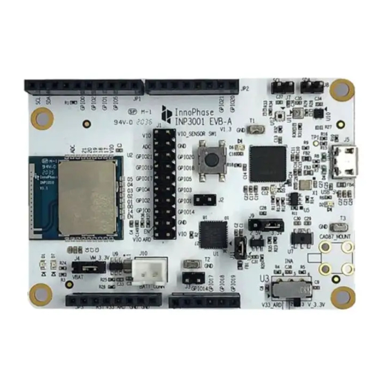
INP301x Package Contents The package contains: 1. INP3010 or INP3011 board 2. Micro USB cable 3. Antenna (INP3011 board only) 4. Battery box Figure 1: INP3011 EVB-A Board with INP1011 module board installed Version 1.1 ©InnoPhase, Inc. 2020... -
Page 6: Description Of The Board
3. Power supply section: Based on the mode, the power for module is derived from either USB or shield header. A battery header is available which can be used as power source as well. 4. On board sensors are available to develop sensor to cloud applications. Version 1.1 ©InnoPhase, Inc. 2020... -
Page 7: Jumpers On The Board
Connect SDA to GPIO3 Select IO voltage for FTDI IOs Battery terminal JP1 to JP4 Arduino UNO shield compatible header (3.3V support only) Switch between Stand-alone mode and Arduino Shield Mode Table 1: Jumper Information Version 1.1 ©InnoPhase, Inc. 2020... -
Page 8: Power Supply And Mode Switch
(U3) selects between USB and Arduino header supply using the common net Vm_3.3V. The jumper J4 is used to select between battery supply and Vm_3.3V. The same jumper can be used for measuring current consumption of the module. Version 1.1 ©InnoPhase, Inc. 2020... -
Page 9: Io Header (J1)
The J1 header brings out all the IOs from INP101x module. These IOs can be used for debug, and/or any external interfacing needs. The pinout of this header is shown in Figure 5. To work with on board sensor, pins 1 & 2 needs to be shorted. Figure 5: IO Header Version 1.1 ©InnoPhase, Inc. 2020... -
Page 10: Shield Headers (Jp1 To Jp4)
3. Remaining GPIOs are available on JP2 and JP4 Note that INP301x supports 2.5V IO as the default configuration. The shield header connections are shown in Figure 6. Figure 6: J1 Pinout Figure 7: Arduino UNO shield compatible jumpers Version 1.1 ©InnoPhase, Inc. 2020... -
Page 11: On Board Sensors
3. Light (TI OPT3002) To use the sensors, J7, J8, pins 1 & 2 of J1 should be connected. This enables power connection to the sensors on board, I2C connection on GPIOs 3 & 4. Version 1.1 ©InnoPhase, Inc. 2020... -
Page 12: Functional Description
The JTAG on A-bus is used for debugging applications on the INP101x module. The UART on C-bus is used for programming the INP101x module. The CONSOLE port is a unidirectional UART from INP101x module that operates at high baud rate of 2457600, used for debug prints. Version 1.1 ©InnoPhase, Inc. 2020... -
Page 13: Driver Installation For Windows Os
On Windows OS, libusbK driver needs to be installed to communicate and control the Talaria TWO module via the FTDI device on the evaluation board. The tools/applications provided by InnoPhase will use this driver. Install/uninstall instructions for this driver is given subsequent sections. - Page 14 User Guide for Talaria TWO Evaluation Board To establish communication with Talaria TWO module via the FTDI device on the InnoPhase Evaluation Board, the Talaria TWO USB driver must be libusbK. In case the current driver is not libusbK, use the drop-down menu to select libusbK and click on Reinstall Driver which will update the drivers to libusbK.
- Page 15 Uninstall instructions for libusbK driver To uninstall libusbK and retrieve COM ports, follow the following steps: 1. Expand the libusbK USB Devices and right click on the InnoPhase T2 Evaluation Board. Click on Update Devices as shown in Figure Figure 11: Device Manager Version 1.1...
- Page 16 User Guide for Talaria TWO Evaluation Board 2. On the new window, click on Let me pick from a list of available drivers on my computer option and click on Next. Figure 12: Update Devices Version 1.1 ©InnoPhase, Inc. 2020...
- Page 17 User Guide for Talaria TWO Evaluation Board 3. Select USB Composite Device Driver and install the same for reinstalling COM posts. Figure 13: Select the device driver Version 1.1 ©InnoPhase, Inc. 2020...
-
Page 18: Shield Mode
EVB-A as Wi-Fi Shield with STM32 Nucleo Board A comprehensive set of host application packages are available to download via ST or InnoPhase websites to demonstrate the use of EVB-A as a Wi-Fi/BLE shield board. Figure 14: INP3010 EVB-A as Wi-Fi Shield Version 1.1... -
Page 19: Power Measurement
J4 or supplying power directly on J4 using specialty power supplies like Otti Arc from Qiotech. Error! Reference source not found. shows the connection setup to measure current consumption u sing Otti Arc. Figure 15: Current measurement setup using Otti Arc Version 1.1 ©InnoPhase, Inc. 2020... -
Page 20: Using Battery As Power Source
User Guide for Talaria TWO Evaluation Board Using Battery as Power Source Header J4 will switch between VBat and Vm_3.3V. Error! Reference source not found. shows VBat c onnection. Figure 16: J4 Header Version 1.1 ©InnoPhase, Inc. 2020... -
Page 21: Antenna
The customer can either use the same part or a part with the same specification or a part with gain < 2.15 dBi and return loss < 17 dBi. If the customer is compliant with the above specification, the FCC certification could be leveraged. Version 1.1 ©InnoPhase, Inc. 2020... -
Page 22: Power Supply
External power can be delivered from battery or a power supply connected to pins 2, 3 and AGND. Voltage from power source should be between 2.7V to 4.0V. Version 1.1 ©InnoPhase, Inc. 2020... -
Page 23: Talaria Two Module Integration In End Products
For specific questions and support need to integrate Talaria TWO into customer platforms, customers are advised to contact InnoPhase Inc. We provide comprehensive support for HW and SW source documentation, design reviews, and verification. -
Page 24: Fcc/Ised Regulatory Notices
User Guide for Talaria TWO Evaluation Board 13 FCC/ISED Regulatory Notices 13.1 Modification Statement Changes or modifications made to this equipment not expressly approved by InnoPhase Inc. may void the FCC authorization to operate this equipment. 13.2 Interference Statement This device complies with Part 15 of the FCC Rules and with Industry Canada license-exempt RSS standard(s). -
Page 25: Rf Exposure Statement For Module Integration
1. The host product with the module installed must be evaluated for simultaneous transmission requirements 2. The user manual for the host product must clearly indicate the operating requirements and conditions that must be observed to ensure compliance with current FCC IC RF exposure guidelines. Version 1.1 ©InnoPhase, Inc. 2020... -
Page 26: Labeling Requirements For The Host Device
être étiqueté pour afficher le FCC ID et IC du module, précédé des mots "Contient le module émetteur", ou le mot "Contient", ou un libellé similaire exprimant la même signification, comme suit: 1. Contient FCC ID: 2AVAL-INP2045 2. Contient IC: 25715-INP2045 Version 1.1 ©InnoPhase, Inc. 2020... - Page 27 User Guide for Talaria TWO Evaluation Board Talaria TWO™ INP1011-A2 HVIN: INP1011 YYWW FCC ID: 2AVAL-INP2045 IC: 25715-INP2045 Version 1.1 ©InnoPhase, Inc. 2020...
-
Page 28: Support
InnoPhase Incorporated takes no responsibility for the content in this document if provided by an information source outside of InnoPhase Incorporated.
Need help?
Do you have a question about the Talaria TWO EVB-A and is the answer not in the manual?
Questions and answers