
Subscribe to Our Youtube Channel
Related Manuals for OSS OSS-PCIe-HIB25-x16


Summary of Contents for OSS OSS-PCIe-HIB25-x16
- Page 1 PCIe x16 Gen2 Host Cable Adapter Model: OSS-PCIe-HIB25-x16 Installation Guide SKU: OSS-PCIe-HIB25-x16 www.onestopsystems.com...
-
Page 2: Table Of Contents
2.1.2 PCIe Slot & Motherboard Requirement 2.1.3 x16 iPass Cable 2.1.4 Expansion Chassis / backplanes 2.1.5 ATX Power Supply 2.2 Software Requirement Installation Procedures Check HBA cards to use Install Host card Install Target card Install PCIe card Install x8 iPass cable OSS-PCIe-HIB25x16| 2... - Page 3 Connect ATX Power Supply Power ON the system Verify Hardware Target card LEDs Host card LEDs Verify Device in Windows OS Software Installation How to Get More Help 7.1 Contacting Technical Support 7.2 Returning Merchandise 7.3 Online Support Resources OSS-PCIe-HIB25x16| 3...
-
Page 4: Preface
Disclaimer: We have attempted to identify most situations that may pose a danger, warning, or caution condition in this manual. However, the company does not claim to have covered all situations that might require the use of a Caution, Warning, or Danger indicator. OSS-PCIe-HIB25x16| 4... -
Page 5: Safety Instructions
Also, before connecting a cable, make sure both connectors are correctly oriented and aligned. CAUTION Do not attempt to service the system yourself except as explained in this manual. Follow installation instructions closely. OSS-PCIe-HIB25x16| 5... - Page 6 Handle all sensitive components at an ESD workstation. If possible, use anti-static floor pads and workbench pads. Handle components and boards with care. Do not touch the components or contacts on a board. Hold a board by its edges or by its metal mounting bracket. OSS-PCIe-HIB25x16| 6...
-
Page 7: Introduction
The PCIe x16 adapter extends the PCIe bus at 80Gb/s with extremely low latency because there is no conversion software. Part numbers: OSS-PCIE-HIB25-x16 (OSS-270) Specifications Item Description... -
Page 8: Overview
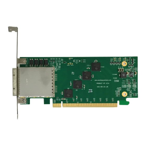
This is an overview on HIB25-x16 card. The card is available it Target and Host versions. The HIB25-x16 target version has four optocouplers mounted on top lest side OSS-386 board. The host version does not have an optocouplers mounted on the board. -
Page 9: Pcie Card Edge
Power is provided by the PCI-e card slot. Power required by internal components of OSS-PCIe-HIB-38-x8 -QUAD is estimated to be 3.75 watts Cable power is to be provided per PCIe cable specification. When an active cable (powered transceiver) is used, additional power is required from the PCI-e card slot. -
Page 10: Board Leds
One Stop Systems Board LEDs There are three LEDs on boards. PWR --Power good, board has power CABLE: Link width CE LINK—Card edge, successful link with the card edge 1.10 Block Diagram OSS-PCIe-HIB25x16| 10... -
Page 11: Signal Direction
One Stop Systems 1.11 Signal Direction 1.12 Dimensions OSS-PCIe-HIB25x16| 11... -
Page 12: Operating Mode
A separate HIB25-x16 card is required to use as target. As shown from the photo below, the Target card has four “Optocouplers” mounted on the board. The target card can only be used as Target and will operate correctly when installed in a Upstream slot of an OSS expansion backplane. -
Page 13: Card Edge Connector Pin Outs
Hot-Plug presence detect PERn7 Receiver differential pair, Lane 7 Ground Ground PET8+ RSVD Reserved PET8- Transmitter differential pair, Lane 8 Ground Ground PER8+ Ground PER8- Receiver differential pair, Lane 8 PET9+ Ground PET9- Transmitter differential pair, Lane 9 Ground OSS-PCIe-HIB25x16| 13... - Page 14 Transmitter differential pair, Lane 14 Ground Ground PER14+ Ground PER14- Receiver differential pair, Lane 14 PET15+ Ground PET15- Transmitter differential pair, Lane 15 Ground Ground PER15+ PRSNT2# Hot-Plug presence detect PER15- Receiver differential pair, Lane 15 RSVD Reserved Ground OSS-PCIe-HIB25x16| 14...
-
Page 15: X16 Cable Connector (Downstream / Upstream)
Power: Provides local power for in-cable redriver circuits. Only needed on long cables (Power does not go across the cable.) PWR_RTN Po Provides local power return path for PWR pins. CWAKE# Cable WAKE CPERST# Cable PCI Express Reset OSS-PCIe-HIB25x16| 15... -
Page 16: Hardware Requirements
NOTE: You need a pair of HIB25-x16, one as target card and the other as host card One x16 iPass cable (connecting between host and target) OSS Expansion chassis with Gen2 / Gen3 backplane, or OSS expansion backplane and power supply. 2.1.1 HIB25-x16 Host and Target Cards You need a pair of HIB25-x16 card, one as host card and the other as target card. -
Page 17: Expansion Chassis / Backplanes
2.1.5 ATX Power Supply If you are using an OSS backplane with the HIB38-x8-DUAL card, you need a power supply unit to provide power. A standard ATX power supply will work with the boards. Software Requirement Computer running Windows 7, 8, 10 and or Server... -
Page 18: Installation Procedures
Prior to using the cards, you need to make sure you have the appropriate host and target cards. The OSS HIB25-x16 host card does not have an optocouplers mounted on the board, see photo below. The OSS HIB25-x15 target card is populated with four optocouplers on the boards, see photo below. -
Page 19: Install Target Card
Install Target card Install the Target card in the OSS expansion backplane. Plug-in the target card in the “Upstream” slot. Do not plug in the target card while expansion unit or the expansion backplane is ON as this can damage the board. Turn OFF the unit first before installing the card. -
Page 20: Install Pcie Card
One Stop Systems Install PCIe card Plug-in your third party PCIe card in the expansion backplane. Use the downstream slot on the OSS backplane. See photos below for the location of the downstream slot / end-point slot. Install x8 iPass cable ... -
Page 21: Connect Cable To Target Card
Connect Cable to Target card Plug in the cable to the Target card. See photos below. 3.5.2 Connect Cable to Host card Plug in the other end of the four cables to the Host card. 3.5.3 Case Diagram OSS-PCIe-HIB25x16| 21... -
Page 22: Connect Atx Power Supply
If you are using an expansion chassis, the power supply is already part of the unit. You can skip this step. If you are using an expansion backplane, plug-in the ATX power supply cable into the 24pin ATX power connector on the OSS board. -
Page 23: Verify Hardware
The host card LEDs will show the same LED status as the target card. PWRGD – Solid green CE LINKED – Solid green or blinking green, depending on the blink rate. Gen3- solid green Gen2 - Blinking frequency: 2Hz Gen1 - Blinking frequency: 1Hz OSS-PCIe-HIB25x16| 23... -
Page 24: Verify Device In Windows Os
In Windows 7 and Windows 10 or Windows Server Device Manager, you should see multiple instances of PCI standard PCI-to-PCI bridge. Right click on the device and select properties, select “Details” tab to view the vendor ID of the board. In this example, the OSS expansion backplane has a PCIe switch with vendor ID of 8733, see photo below. - Page 25 One Stop Systems If you are connecting or using an OSS expansion backplane without a PCIe switch or PCIe bridge (i.e. 1slot board), the only device that will be recognized or detected in Windows device manager is the end-point card, which is the 3 party PCIe card populating the end-point slot / downstream on the backplane.
-
Page 26: Software Installation
One Stop Systems Software Installation No software or driver is required for the Host Adapter card. OSS-PCIe-HIB25x16| 26... -
Page 27: How To Get More Help
If you need technical support, product assistance or have a technical inquiry we encourage you to submit it on-line using our Technical Support Form. If you need to send a unit for repair or diagnostic evaluation, fill out our RMA (Return Material Authorization) online request form. https://www.onestopsystems.com/support OSS-PCIe-HIB25x16| 27... - Page 28 One Stop Systems OSS-PCIe-HIB25x16| 28...
Need help?
Do you have a question about the OSS-PCIe-HIB25-x16 and is the answer not in the manual?
Questions and answers