
Related Manuals for Munro Complete PRO II


Summary of Contents for Munro Complete PRO II
- Page 1 OWNER’S MANUAL Self-Cleaning Basket Strainers PARTS - DRAWINGS - DIMENSIONS - SPECIFICATIONS CP01R8 0421 © 2021 MUNRO COMPANIES INC., ALL RIGHTS RESERVED...
- Page 3 TABLE OF CONTENTS Complete PRO II Assembly Guide Munro LP Series Pump Operation & Maintenance Munro SmartBox Reduced Incoming Amperage Warranty Statement Enclosure Dimensions...
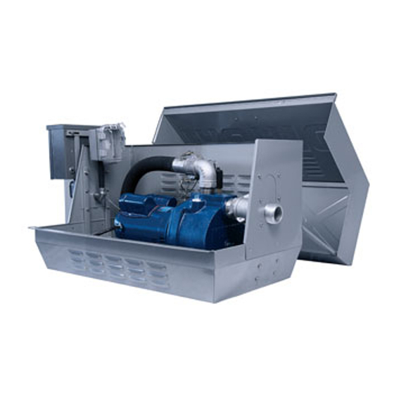
- Page 5 Munro Complete PRO ll ASSEMBLY GUIDE PARTS discharge assembly side discharge knockouts (2) electrical outlet assembly PSR control box suction assembly pressure gauge & sensor assembly bottom discharge knockouts (2) sensor wire and boot temp sensor (stored inside outlet housing)
- Page 6 Munro Complete PRO ll ASSEMBLY GUIDE Step 1 – Preparing the enclosure for irrigation system access knockouts 1. Using a hammer and pliers, remove the appropriate discharge knockout from the CP unit – concentrating on the two metal tabs. Side Knockout 2.
- Page 7 Munro Complete PRO ll ASSEMBLY GUIDE Step 2 – Setting and finalizing the pump (Continued) 4. Locate the sensor wire and boot inside the electrical outlet assembly. 5. Connect the quick disconnect fittings, closest to the rubber boot, to the pressure sensor. Cover this connection with the boot by sliding it into place.
- Page 8 Munro Complete PRO ll ASSEMBLY GUIDE Changing the direction of the pump To meet your installation requirements, you can change the side through which the electrical and suction enter the enclosure. Use caution. Some edges may be sharp! Step 1 – Remove the suction pass-through panel 1.
- Page 9 Munro Complete PRO ll ASSEMBLY GUIDE Step 2 – Remove the electrical assembly (Continued) 5. Using a screwdriver, remove the cover plate from the SLB. 6. Out of the bottom, pull the wires from the pump control box through the chase nipple and SLB.
- Page 10 Munro Complete PRO ll ASSEMBLY GUIDE Step 4 – Reconnecting the electrical assembly on the opposite side (Continued) 2. With the electrical outlet assembly on the inside, feed the outlet assembly wires and pipe nipple through the round hole on the electrical pass-through panel of the enclosure.
- Page 11 Munro Complete PRO ll ASSEMBLY GUIDE Step 5 – Changing the Pump Direction (Continued) Pressure Gauge and Pressure Sensor 3. Use a wrench to remove the pressure gauge and sensor assembly from back-side opening. 4. Relocate the gauge and pressure sensor assembly to the opposite (now front facing) side of the pump, ending parallel to pump motor.
- Page 12 WILL cause serious personal injury, death or major property damage if ignored. ROTATION 1. When facing the suction tapping, all Munro pumps run in a warns about hazards that CAN cause serious Counter-Clockwise (CCW) rotation only. Rotation from the personal injury, death or major property damage if ignored.
- Page 13 1. Drain the entire system if there is a danger of freezing. start-up or operation of this pump. 2. Drain plugs are provided in both upper and lower pump Toll Free: 1.800.942.4270 case chambers. 3. Filling the pump with non-toxic Munro Freeze Defeat and...
- Page 14 Munro LP Series Pump OPERATION & MAINTENANCE PUMP PERFORMANCE LP Series 3/4 HP - 3 HP Capacity - U.S. Gallons per Minute Shut Off Suction Discharge Max ▲ Discharge Pressure (PSI) at 5’ Suction Lift Pressure Pipe Pipe Suction Lift 2”...
- Page 15 Munro LP Series Pump OPERATION & MAINTENANCE PUMP SPECIFICATIONS LP Series 3/4 HP - 3 HP Motor Voltage Service Factor Motor Amps Type Volts/Amps (Factory) Liquid Single Phase Three Phase Connected Temperature 115V 208V 230V 208V 230V 460V 11.6 16.6...
- Page 16 Munro LP Series Pump OPERATION & MAINTENANCE PUMP DIMENSIONS LP Series 3/4 HP - 3 HP Discharge Suction 1 1/2” 2” 19 3/4” 3 5/8” 4 1/4” 8 1/2” 7 1/2” 9 1/2” 10 7/8” 9 1/2” 2 3/8” 4 3/4”...
- Page 17 Munro LP Series Pump OPERATION & MAINTENANCE PARTS BREAKDOWN LP Series 3/4 HP - 3 HP ITEM SINGLE HORSEPOWER 1 1/2 PHASE MODEL NO. LP075B LP100B LP150B LP200B LP300B DESCRIPTION PART NO. Motor, Nema J - 1 Phase MLP119370 MLP119399...
- Page 18 Munro LP Series Pump OPERATION & MAINTENANCE PARTS BREAKDOWN LP3005 ITEM SINGLE PHASE HORSEPOWER MODEL NO. LP3005B DESCRIPTION PART NO. Motor, NEMAJ - 1 Phase MLP131641 ▲ Slinger, Washer MLPG005 Shaft Sleeve MLP60010 Mount Ring MLP3300 ▲ Hex HD Cap Screws 3/8” x 3/4”...
- Page 19 Munro LP Series Pump OPERATION & MAINTENANCE TROUBLESHOOTING GUIDE SYMPTOM POSSIBLE CAUSE(S) CORRECTIVE ACTION Little or no discharge 1. Casing not initially filled with water to prime pump 1. Fill pump casing 2. Total head too high 2. Shorten suction lift and/or change head 3.
- Page 20 Munro SmartBox Reduced Incoming Amperage OPERATION & MAINTENANCE Typical SmartBox Installation NOTE: Refer to specific wiring diagram located on inside cover of enclosure. Turn Breaker “OFF” • Never work with electrical wiring on a live circuit. Plumb for Sensors • Pressure Sensor - 1/4” NPT •...
- Page 21 Munro SmartBox Reduced Incoming Amperage OPERATION & MAINTENANCE System Fill Tip • Timer inside the SmartBox is preset at 30 seconds. Initial start-up or large zones may require additional time. • To temporarily increase cycle time, turn the timer dial 1/4 turn to the right.
- Page 22 Munro SmartBox Reduced Incoming Amperage OPERATION & MAINTENANCE Troubleshooting Guide - SmartBox Did Did You Know? During a normal run cycle, no lights should be lit on the time delay. Should a sensor detect a possible system problem, the “on” light will engage. If the system is shut down during a cycle both the “on”...
- Page 23 (additional cost). If on-site start up is selected or required, Munro will supply start up assistance for the time needed to commission the pump Further, we warrant to our immediate customer and to the ultimate consumer (the “Customer”) station, up to one day including travel to and from the job site (unless otherwise noted).
- Page 24 ENCLOSURE DIMENSIONS " 8 " 8 " " NOTE: Inlet hole is a 2” x 2 ” knockout 10 1 " 4 " 8 " NOTES...
Need help?
Do you have a question about the Complete PRO II and is the answer not in the manual?
Questions and answers