
Related Manuals for WTI RPC-4850-8N

Summary of Contents for WTI RPC-4850-8N
- Page 1 Distributed by i-Tech Company LLC TOLL FREE: (888) 483-2418 • EMAIL: info@i-techcompany.com • WEB: www.i-techcompany.com...
- Page 3 Warnings and Cautions: INSTALLATION INSTRUCTIONS SECURE RACKING If Secure Racked units are installed in a closed or multi-unit rack assembly, they may require further evaluation by Certification Agencies. The following items must be considered. The ambient within the rack may be greater than room ambient. Installation should be such that the amount of air flow required for safe operation is not compromised.
- Page 4 RPC-4850-8N Remote Power Controller - User’s Guide...
-
Page 5: Table Of Contents
3.2. Communicating with the RPC-4850-8N ....... . 3-2 Installation ............4-1 4.1. - Page 6 3.1 . . RPC-4850-8N Block Diagram ........
-
Page 7: Introduction
1. Introduction Electronic equipment sometimes "locks-up," requiring a service call just to flip the power switch to perform a simple reboot. The RPC-4850-8N Heavy Duty Remote DC Power Controller gives you the ability to perform this function from anywhere, just point your browser to the RPC’s IP address, enter the secure password, and you’re just a click away from remote power and... - Page 8 RPC-4850-8N Remote Power Controller - User’s Guide Typographic Conventions Throughout this manual, typefaces and characters have been used to denote the following: COURIER FONT Indicates characters typed on the keyboard. For example, /ON 3 or /OFF 4. [Bold Font] Text set in bold face and enclosed in square brackets...
-
Page 9: Unit Description
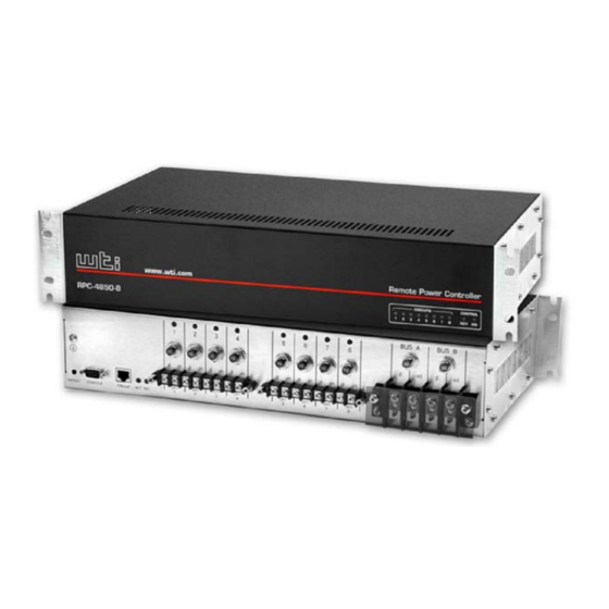
2. Unit Description 2.1. Front Panel Components As shown in Figure 2.1, the RPC-4850-8N front panel includes the following: www.wti.com Remote Power Controller RPC-4850-8 CIRCUITS CONTROL Figure 2.1: RPC-4850-8 Front Panel Circuit Status Indicators: A series of eight LED indicators, which light ➀... -
Page 10: Back Panel
RPC-4850-8N Remote Power Controller - User’s Guide 1 2 3 4 BUS A BUS B Ø Ø Ø Ø Ø Ø Ø Ø Ø Ø DEFAULT CONSOLE 10BaseT ACT RDY Figure 2.2: Back Panel Console Port: A DB9, RS232 serial port (DTE), for connection to a local ➂... -
Page 11: Quick Start
50 Amps. Once power is applied to the unit, the ON LED should light, and the RDY LED should begin to flash. This indicates that the RPC-4850-8N is ready to receive commands. - Page 12 RPC-4850-8N Remote Power Controller - User’s Guide NETWORK INPUT 10BASE-T RS232 INPUT DC/DC CONVERTER ISOLATED CONTROL POWER LOGIC SUPPLY LOGIC RL1 RL2 ... GROUND -48 VDC INPUT A 0 VDC -48 VDC INPUT B (CIRCUIT 0 VDC BREAKER) OUTPUT -48 VDC...
-
Page 13: Connect Your Pc To The Rpc-4850-8N
3.2. Communicating with the RPC-4850-8N The RPC-4850-8N offers two separate user interfaces: the Web Browser Interface and the Text Interface. The Web Browser interface allows you to contact the unit via a TCP/IP network, using a standard, JavaScript enabled web browser (such as Internet Explorer.) The Text Interface consists of a... -
Page 14: Circuit Status Screen - Web Browser Interface (Sample Values Show)
RPC-4850-8N Remote Power Controller - User’s Guide Figure 3.2: Circuit Status Screen - Web Browser Interface (Sample Values Show) Remote Power Controller v1.41i Site ID: (undefined) | Name | Password | Status | Boot/Seq. Delay | Default | -----+------------------+-------------+--------+-----------------+---------+ | (undefined) | (undefined) - Page 15 Quick Start Text Interface: Via Telnet: Telnet to the RPC’s default IP address (192.168.168.168). The Circuit Status Screen (Figure 3.3) should be displayed. Via Local PC: Start your communications program and then press [Enter]. The Circuit Status Screen should be displayed as shown in Figure 3.3.
- Page 16 Web Browser Interface: Click on the "Log Out" button. Text Interface: Type /X and press [Enter]. This completes the Quick Start procedure for the RPC-4850-8N. Please proceed to Section 4 and Section 5 for complete installation and configuration instructions.
-
Page 17: Installation
This Section provides further details regarding installation of the RPC-4850-8N unit. 4.1. Power Supply Connection Connect the RPC-4850-8N unit to an appropriate -48 VDC, 50 Amp power supply as shown in Figure 3.1. The RPC includes two separate -48 VDC DC inputs; connect power cables to the unit's Circuit "A"... -
Page 18: Connecting Switched Devices To The Rpc-4859-8N
RPC-4850-8N Remote Power Controller - User’s Guide 4.2 Connecting Switched Devices to the RPC-4859-8N Make certain that the power supply to the RPC unit is switched Off, and then connect the supply cables from your -48 VDC powered devices to the Switched Output Circuits on the RPC back panel. -
Page 19: Configuration
5. Configuration 5.1. System Mode and User Mode In order to restrict access to sensitive command functions, the RPC-4850-8N features two operating modes; System Mode and User Mode. • System Mode: Allows access to all configuration menus, switching functions, reboot functions and status screens. The System Mode Status Screens show On/Off conditions for all switched circuits, and lists all currently defined system parameters. -
Page 20: Communicating With The Rpc-4850-8N
RPC-4850-8N Remote Power Controller - User’s Guide Figure 5.1: Circuit Status Screen - Web Browser Interface 5.2. Communicating with the RPC-4850-8N In order to configure the unit or invoke command functions, you must first connect to the RPC and access command mode. As discussed in previously, the RPC offers two separate command interfaces: the Web Browser Interface, and the Text Interface. -
Page 21: Accessing The Text Interface
Confi guration Password Prompt: The RPC will display a prompt, which asks for your name and password. User Name: If you have not previously defined a user name, then this field should be left blank. A user name is only required when one has been defined via the General Parameters menu. -
Page 22: Circuit Status Screen - Text Interface
RPC-4850-8N Remote Power Controller - User’s Guide Remote Power Controller v1.41i Site ID: (undefined) | Name | Password | Status | Boot/Seq. Delay | Default | -----+------------------+-------------+--------+-----------------+---------+ | (undefined) | (undefined) 0.5 Secs | (undefined) | (undefined) 0.5 Secs | (undefined) | (undefined) -
Page 23: Configuration Menus
Confi guration 5.3. Configuration Menus As described in the sections that follow, configuration parameters for the RPC can be selected via the Web Browser Interface or Text Interface. Although the Web Browser Interface and Text Interface provide two separate means for selecting parameters, both allow access to essentially the same set of parameters, and parameters selected via one interface will also be applied to the other. -
Page 24: The General Parameters Menus
RPC-4850-8N Remote Power Controller - User’s Guide Figure 5.3: General Parameters Menu - Web Browser Interface 5.3.1. The General Parameters Menus The General Parameters Menus allow you to select parameters such as the System Password, User Name, Site I.D. and other options. -
Page 25: General Parameters Menu - Text Interface
Confi guration GENERAL PARAMETERS: System Password: (undefined) User Name: (undefined) Site ID: (undefined) Command Echo: Inactivity Timeout: 2 Mins Command Confirmation: Automated Mode: Manual Switch Button: On Command Prompt: Default Parameters Enter Selection, Press <ESC> to Exit ... Figure 5.4: General Parameters Menu - Text Interface •... - Page 26 RPC-4850-8N Remote Power Controller - User’s Guide • Inactivity Timeout: Determines how long the RPC will wait for additional commands during periods of inactivity. When the Timeout Period elapses, the user will be disconnected from command mode. (Default = 2 Minutes.) •...
-
Page 27: The Serial Parameters Menu
Confi guration Figure 5.5: Serial Parameters Menu - Web Browser Interface SERIAL PARAMETERS: 1. Baud Rate: 9600 2. Data: 8 Bit 3. Parity: None 4. Stop: 1 Bit 5. Port Mode: Console 6. Modem Init. Str: ATE0M0Q1&C1&D2S0=1 Enter selection, Press <ESC> to return to previous menu ... Figure 5.6: Serial Parameters Menu - Text Interface 5.3.2. - Page 28 RPC-4850-8N Remote Power Controller - User’s Guide As shown in Figure 5.5 and Figure 5.6, the Serial Parameters Menus allow you to define the following parameters: • Baud Rate: Baud Rate for the RPC Console Port. (Default = 9600 bps.) Note: When this setting is changed, the new baud rate will not be applied until the user exits and then re-enters command mode.
-
Page 29: Circuit Parameters Menus
Confi guration Figure 5.7: Circuit Parameters Menu - Web Browser Interface CIRCUIT #1 PARAMETERS: 1. Circuit Name: (undefined) 2. Password: (undefined) 3. Boot/Seq. Delay: 0.5 Secs 4. Power Up Default: Enter Selection, Press <ESC> to Exit ... Figure 5.8: Circuit Parameters Menu - Text Interface (Circuit 1 Shown) 5.3.3. -
Page 30: Circuit Passwords And Co-Location Features
RPC-4850-8N Remote Power Controller - User’s Guide The Circuit Parameters Menu allows you to define the following parameters: • Circuit Name: (Up to 16 Characters, Default = undefined.) Note: Circuit Names cannot begin with a number, dash (-), underscore character (_), slash character (/) or backslash character (\), and cannot include non-printable characters, asterisks (*), colons (:), "plus"... -
Page 31: The Boot / Sequence Delay Period
Confi guration 5.3.3.2. The Boot / Sequence Delay Period. The Boot / Sequence Delay value will be applied differently for reboot operations as opposed to simple On/Off operations as described below: Reboot Cycles: Single Circuit: The Boot/Seq. Delay determines how long the circuit will remain Off before it is switched back On again. -
Page 32: Network Parameters Menu - Web Browser Interface
RPC-4850-8N Remote Power Controller - User’s Guide Figure 5.9: Network Parameters Menu - Web Browser Interface NETWORK PARAMETERS: 1. IP Address: 207.212.30.80 2. Subnet Mask: 255.255.255.0 3. Gateway Address: 207.212.30.1 4. Send MSS: 5. IP Security MAC Address: 00-09-9b-00-90-dd Enter Selection, Press <ESC>... -
Page 33: Network Parameters Menus
Confi guration 5.3.4. Network Parameters Menus The Network Parameters Menus are used to select the IP Address, Subnet Mask, Gateway Address and other network parameters. • Web Browser Interface: Click the "Setup" button to access the Setup Menus, and then click the "Network Parameters" button. The Network Parameters Menu will be displayed as shown in Figure 5.9. -
Page 34: Ip Security Feature
RPC-4850-8N Remote Power Controller - User’s Guide IP SECURITY: Security Mask #1: (undefined) Mask #1 Action: Permit Security Mask #2: (undefined) Mask #2 Action: Permit Security Mask #3: (undefined) Mask #3 Action: Permit Security Mask #4: (undefined) Mask #4 Action:... - Page 35 Confi guration Example 1: Deny access to all hosts except 192.1.1.5: Security Mask #1: 255.255.255.255 Mask #1 Action: Deny Security Mask #2: 192.1.1.5 Mask #2 Action: Permit Since 255 is a wild card, Mask #1 blocks all IP Addresses. Mask #2 then specifically grants access to 192.1.1.5 only.
-
Page 36: The Telnet Parameters Menus
RPC-4850-8N Remote Power Controller - User’s Guide Figure 5.12: Telnet Parameters Menu - Web Browser Interface TELNET PARAMETERS: 1. Service: 2. Telnet Port #: Enter Selection, Press <ESC> to Exit ... Figure 5.13: Telnet Parameters Menu - Text Interface 5.3.5. -
Page 37: Web Server Parameters Menus
Confi guration Figure 5.14: Web Server Parameters Menu - Web Browser Interface WEB SERVER: 1. Service: 2. Server Port #: Enter Selection, Press <ESC> to Exit ... Figure 5.15: Web Server Parameters Menu - Text Interface 5.3.6. Web Server Parameters Menus The Web Server Parameters Menus are used to configure the internal web server, which allows the unit to be operated via the Web Browser Interface. -
Page 38: Save Configuration Parameters
RPC-4850-8N Remote Power Controller - User’s Guide 5.4. Save Configuration Parameters The RPC offers two methods for saving parameters; Saving to Memory, and Saving to an ASCII File. Saving parameters to memory ensures that your user-defined configuration will remain intact if power to the RPC is temporarily interrupted. After the configuration menus have been used to change parameters, the RPC will... -
Page 39: Operation
6. Operation As discussed in Section 5, the RPC-4850-8N offers two separate command interfaces; the Web Browser Interface and the Text Interface. Note that both command interfaces offer essentially the same options and features, and that parameters defined via the Web Browser Interface will also apply when communicating via the Text Interface (and vice versa.) - Page 40 RPC-4850-8N Remote Power Controller - User’s Guide Figure 6.1: Circuit Status Menu - Web Browser Interface (Sample Values Shown) Switching Circuits On: Click the "On" radio button next to the desired circuit(s), then click "Apply". To switch all circuits On, click the "On"...
-
Page 41: Operation Via The Text Interface
Operation Remote Power Controller v1.41i Site ID: (undefined) | Name | Password | Status | Boot/Seq. Delay | Default | -----+------------------+-------------+--------+-----------------+---------+ | (undefined) | (undefined) 0.5 Secs | (undefined) | (undefined) 0.5 Secs | (undefined) | (undefined) 0.5 Secs | (undefined) | (undefined) 0.5 Secs | (undefined) -
Page 42: Switching And Reboot Commands - Text Interface
RPC-4850-8N Remote Power Controller - User’s Guide Remote Power Controller v1.41i Site ID: (undefined) Display Configuration Display Help Screen View/Set General Parameters Display Circuit Status /P [n] View/Set Circuit Parameters Display Network Status View/Set Serial Parameters View/Set Network Parameters Control... - Page 43 Operation To Switch Circuits On or Off, initiate a boot cycle, or set circuits to Power Up Default values, proceed as follows: Switch Circuit(s) On: To power-on a circuit, type /ON n and press [Enter]. Where "n" is the number or name of the desired circuit. For example: /ON 1 or /ON ROUTER Switch Circuit(s) Off: To power-off a circuit, type /OFF n and press...
-
Page 44: Applying Commands To Several Circuits - Text Interface
RPC-4850-8N Remote Power Controller - User’s Guide 6.2.3. Applying Commands to Several Circuits - Text Interface As described below, switching commands can be applied to only one switched DC circuit, or to an assortment of circuits. Note: When switching operations are initiated, Boot/Sequence Delay times will be applied as described in Section 5.3.3.2. -
Page 45: The Automated Mode
Operation 6.4. The Automated Mode The Automated Mode allows the RPC to execute switching commands, without displaying menus or generating response messages. Automated Mode is designed to allow the RPC to be controlled by a device which can generate commands to control power switching functions without human intervention. When Automated Mode is enabled, the /ON, /OFF, /BOOT, and /X commands are executed without a "Sure?"... -
Page 46: Manual Operation
RPC-4850-8N Remote Power Controller - User’s Guide "Sure?" Prompt Suppressed: All commands are executed without prompting for user confirmation. Some Error Messages Suppressed: If the [Enter] key is pressed without entering a command, the RPC will not respond with the "Invalid Command"... -
Page 47: Saving And Restoring Configuration Parameters
7. Saving and Restoring Configuration Parameters After the RPC-4850-8N has been properly configured, parameters can be downloaded and saved as an ASCII text file on your local or remote PC. Later, if the configuration is accidentally altered, the file with the saved parameters can be uploaded to automatically reconfigure the unit without the need to... -
Page 48: Restoring Saved Parameters
RPC-4850-8N Remote Power Controller - User’s Guide 7.2. Restoring Saved Parameters This Section describes the procedure for using your communications program to send saved parameters to the RPC. Note: Parameters saved to an ASCII file can only be restored via the Text Interface. -
Page 49: Upgrading The Rpc Firmware
Obtain the update file. Firmware modifications can either be mailed to the customer on a CDR, or downloaded from WTI. Place the upgrade CDR in your disk drive or copy the file to your hard drive. - Page 50 Console Port to 9600 bps, Eight Data Bits, No Parity, One Stop Bit, and then return to step 3 above and repeat the upload procedure. When firmware upgrades are available, WTI will provide the necessary files via download or mailed CDR. At that time, an updated Users Guide or...
-
Page 51: Interface Description
A. Interface Description A.1. Serial Console / RS232 Port Interface Figure A.1: Console Port Interface Apx-1... -
Page 52: Specifications
RPC-4850-8N Remote Power Controller - User’s Guide B. Specifications Power Input / Output: • Voltage: -48 VDC • DC Inputs: Two (2); Bus A and/or Bus B, 50-Amps Maximum per Bus. ▪ Connector: Terminal Block; #10 Screws • DC Output Circuits: Eight (8) ▪... -
Page 53: Customer Service
If the unit should need to be returned for factory repair it must be accompanied by a Return Authorization number from Customer Service. WTI Customer Service 5 Sterling Irvine, California 92618... - Page 54 RPC-4850-8N Remote Power Controller - User’s Guide Trademark and Copyright Information WTI and Western Telematic are trademarks of Western Telematic Incorporated. All other product names mentioned in this publication are trademarks of their respective companies. Information and descriptions contained herein are the property of Western Telematic, Inc..
-
Page 55: Index
Index 100Base-T Data Bits 5-10 10Base-T Default 6-2, 6-5 Default Button 2-1, 5-8 Default Circuit Status 5-12 Activity Indicator Default IP Address Automated Mode 5-8, 6-7 to 6-8 Default Parameters Delay Period 5-13 Baud Rate 5-10 Deny 5-16 Boot/Sequence Delay 5-12 to 5-13 Error Messages Circuit Breakers... - Page 56 RPC-4850-8N Remote Power Controller - User’s Guide Service Network Parameters 5-15 to 5-16 Customer Service Apx-3 Network Port 2-2, 4-2 Telnet 5-18 Web Server 5-19 Site I.D. Operation 6-1 to 6-8 Status Indicators Web Browser Interface 6-1 to 6-2 Stop Bits...
- Page 57 Notes: Notes-1...
- Page 58 RPC-4850-8N Remote Power Controller - User’s Guide Notes Notes-2...
Need help?
Do you have a question about the RPC-4850-8N and is the answer not in the manual?
Questions and answers