Table of Contents

Subscribe to Our Youtube Channel
Related Manuals for MDC ROBSON XTT


Summary of Contents for MDC ROBSON XTT
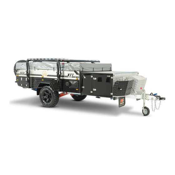
- Page 1 ROBSON XTT DUAL FOLD OVERLAND TENT TOP CAMPER OWNER’S MANUAL U.S.A. EDITION: 2021 - Version 1 www.mdcusa.com * January 2020 Model shown. Phone: 833 632 8721 Copyright © MDC Caravans and Campers INC 2021 All Rights Reserved...
- Page 2 Your use of this Owner’s Manual does not constitute any right or license for you to use MDC’s or any other party’s service marks or trademarks, without the prior written permission of MDC or the applicable party.
- Page 3 TIRE SIZE: DEALER PH: DISCLAIMER: By receiving this handbook, you confirm there you have read and agree to all the terms and conditions and understood the use and maintenance care of MDC Campers and Caravans Inc. www.mdcusa.com Ph: 833 632 8721...
-
Page 4: Table Of Contents
Steps for Determining Correct Load Limit - Trailer Specifications ............. 21 Trailer ..................10 MDC Contact Details and Stores ......... 21 Trailers 10,000 Pounds GVWR or less ....10 Using Your Trailer ..............22 Steps for Determining Load Limit - Instructional Videos ............ - Page 5 Post Winter ................37 Decalcification ................. 58 Trailer Body Maintenance ........... 38 Water Supply ..............67 Mechanical Maintenance ..........38 Water Pumps ................ 67 Wheels and Tires ............38 Switch Supply Tanks............67 Brakes ..................38 Fresh Water Tanks ............68 Brake Adjustment ...............
-
Page 6: General Safety Information
MDC trailers are manufactured using many third party supplied products which have separate manuals. These manual must be read in conjunction with this document and all instructions followed. If your trailer does not have additional... -
Page 7: Reporting Safety Defects
If you believe that your vehicle has a defect that could cause a crash or could cause injury or death, you should immediately inform the National Highway Traffic Safety Administration (NHTSA) in addition to notifying MDC Caravans and Campers INC. -
Page 8: Terminology & Abbreviations
Terminology & Abbreviations Dry Weight: The total weight of the trailer (load on tires plus coupling load) with all options and fittings as supplied by the manufacturer, with empty water tanks, excluding fluids not essential for operation on public roads, and without luggage or personal effects. - Page 9 Toe can be measured in linear units, at the front or rear of the tire, or as an angular deflection. In the case of MDC products, the “toe in”...
-
Page 10: Tire Safety Information
Tire Safety Information This section of the User Manual contains tire safety information as required by 49 CFR 575.6. “Steps for Determining Correct Load Limit – Trailer” “Steps for Determining Correct Load Limit – Tow Vehicle” Section 2.3 has information from the NHTSA brochure titled “Tire Safety – Everything Rides On It” The following brochure information is contained: •... -
Page 11: Steps For Determining Load Limit - Tow Vehicle
Steps for Determining Load Limit - TOW VEHICLE Locate the statement, “The combined weight of occupants and cargo should never exceed XXX lbs., ” on your vehicle’s placard. Determine the combined weight of the driver and passengers who will be riding in your vehicle. Subtract the combined weight of the driver and passengers from XXX kilograms or XXX pounds. -
Page 12: Understanding Tire Pressure And Load Limits
Understanding Tire Pressure and Load Limits Tire inflation pressure is the level of air in the tire that provides it with load-carrying capacity and affects the overall performance of the vehicle. The tire inflation pressure is a number that indicates the amount of air pressure–... -
Page 13: Tire Tread
Tire Tread The tire tread provides the gripping action and traction that prevent your vehicle from slipping or sliding, especially when the road is wet or icy. In general, tires are not safe and should be replaced when the tread is worn down to 1/16 of an inch. -
Page 14: Treadwear Number Utqgs Information
Next number This two-digit number, known as the aspect ratio, gives the tire’s ratio of height to width. Numbers of 70 or lower indicate a short sidewall for improved steering response and better overall handling on dry pavement. The “R” stands for radial. Radial ply construction of tires has been the industry standard for the past 20 years. Next number This two-digit number is the wheel or rim diameter in inches. -
Page 15: Additional Information On Light Truck Tires
Additional Information on Light Truck Tires Please refer to the following diagram. Tires for light trucks have other markings besides those found on the sidewalls of passenger tires. The “LT” indicates the tire is for light trucks or trailers. An “ST” is an indication the tire is for trailer use only. Max. -
Page 16: Tire Pressure Table
Tire Pressure Table Trailer Weight Pressure PSI Pressure KPA 3750lb/1700kg 39psi 272Kpa 3970lb/1800kg 42psi 288Kpa 4190lb/1900kg 44psi 304Kpa 4409lb/2000kg 46psi 320Kpa 4600lb/2100kg 49psi 338Kpa 4850lb/2200kg 352Kpa 5070lb/2300kg 365Kpa Propane Safety Appliances in your trailer are fueled with propane. Propane is heavier than air which will allow it to pool in some areas creating an explosion risk. -
Page 17: Propane Cylinder Safety
Propane Cylinder Safety • Propane Gas cylinders have a 12-year lifespan between inspection and re-certification. Always use gas cylinders that are within their compliance date. • For drawbar mounted cylinders (if applicable), orient the cylinder relief valves of both cylinders discharge away from both the trailer and towing vehicle as shown. -
Page 18: Electrical Safety
Electrical Safety WARNING Failure To Follow These Instructions May Result In Death Or Serious Injury! • When working with electrical equipment or lead acid batteries, have someone nearby in case of an emergency. • Study and follow all the manufacturer’s specific precautions when using and servicing the battery and connected appliances. -
Page 19: General Safety
General Safety Brakes WARNING Your trailer brakes must be maintained and adjusted to operate correctly at all times. Failure to maintain and adjust brakes as outlined in the maintenance schedule may result in a failure causing death or serious injury. Brake Controller Your trailer is fitted with drum type electric brakes. -
Page 20: Jacking Your Trailer
Jacking Your Trailer Your trailer is fitted with purpose built jacking points and from January 2021 supplied with a suitable jack. An appropriately rated bottle jack is an acceptable alternative, however when using the jacking point beneath the trailing arm ensure the jack is of a retracted height that will fit under the jacking point when the tire is deflated. A suitably rated “High Lift”... -
Page 21: Trailer Specifications
INVERTER AIMS Power 1500 watt Pure Sine POWER OUTLETS 2 x 12V x 6 & 2 USB, 110V SOLAR 120W regulated MDC Contact Details and Stores CALIFORNIA ARIZONA Los Angeles 3908 East Broadway Rd. 8420 Kass Dr. Suite 100 Phoenix, AZ 85040... -
Page 22: Using Your Trailer
Using Your Trailer NOTICE Instructions below are for your safety and the avoidance of accidental damage to the trailer through misuse. Follow all directions given in this manual and the manuals for third party products installed. The manufacturer has produced product specific video content for tutorial purposes, to assist in the correct setup and use. -
Page 23: Connecting To The Tow Vehicle
Connecting to the Tow Vehicle WARNING WARNING – Your coupler MUST be rated for the Gross Vehicle Weight and be in serviceable condition. • The hitch MUST be correctly load rated. • Hitch and pin MUST be compatible. • All bolts and fittings must be correctly tightened and serviceable condition. -
Page 24: Hitch
Hitch How to Hitch your coupling. Here is a short guide on how to safely use your coupling to couple and uncouple the trailer from the towing vehicle. Make sure the handbrake is applied prior to coupling and uncoupling. www.mdcusa.com Ph: 833 632 8721... - Page 25 Make sure the dust cap is securely connected to the bump cover. This is done by locating the rear lip on the dust cap onto the groove of the bump cover and then pushing it in a downward motion until the dust cover is secure (there should be a slight click when it has been assembled correctly) Test if the dust cover is connected to the bump cover by applying a slight upward force to the dust cover, it shouldn’t separate.
-
Page 26: Coupling
Coupling STEP 1 Push down the button (1) and push the locking mechanism back (2). When the locking mechanism (2) is all the way back, release the button (1) locking the plate in place STEP 2 Offer up the tow pin to the coupling making sure the tow pin cover is removed and there is no visible debris on it. Locking plate should be in unlocked position as shown. - Page 27 STEP 3 Make sure the tow pin is seated inside the universal and the tow pin top is sticking out of the locking mechanism (see below). Press the button (1) to release the locking mechanism there will be an audible locking noise at which point the mechanism will return to the initial position as shown in step 1.
-
Page 28: Uncoupling
Uncoupling STEP 1 Push down the button 1 and push the locking mechanism back 2. When the locking mechanism is all the way back release the button while holding the mechanism to ensure it does not spring back to the locked position. STEP 2 Lift the coupling up off the tow pin. -
Page 29: Connecting Wiring
Connecting Wiring When connecting ensure the electric cables to your tow vehicle cannot drag on the road or foul the coupling. If necessary, use zip ties or like keep them neat and safe from damage. Connecting the Safety Chains Chains should be crossed over and connected with suitable rated shackles. Ensure they are connected in a way to prevent them dragging on the road but not too tight as to restrict the articulation of the vehicle and trailer combination. -
Page 30: Loading Your Trailer
Loading Your Trailer Loading your trailer can have an effect on the overall handling of the trailer and tow vehicle combination. Loading affects ball mass and balance which must be taken into consideration. • DO NOT exceed the Gross Vehicle Weight Rating (GVWR) •... -
Page 31: Operating Trailer Features
Operating Trailer Features This sections covers details on using the common features on your trailer correctly. Stabilizer Legs The stabilizer legs are fitted to make the trailer stable when occupied. Important things to not are: • Always try to set the stabilizers up in a vertical position, 90 degrees to the chassis as shown in figure below. -
Page 32: Using The Slide Out Kitchen
Using the Slide Out Kitchen Before sliding out kitchen, raise the pad bolt and turn to lock in the up position (Fig: 2) Push down blue latch on the slide mechanism and pull kitchen out. (Fig: 2a) Fig: 2 Fig: 2a When kitchen is extended fit the support leg into its receiver (Fig: 3) Extend support leg and secure locking screw (Fig: 3a) Fig: 3... -
Page 33: 12 Volt Electrical System
12 Volt Electrical System Control Panel Control Panel Use Main Rotary Switch: This is used to switch on or isolate the entire 12 volt system. Circuit Breakers: The round rubber capped Circuit breakers are resettable. To reset the circuit push in the rubber cap. Each circuit breaker is marked with applicable circuit. -
Page 34: Towing Your Trailer
Towing Your Trailer Driving dynamics change considerably when towing a trailer. Many facets of driving need to be modified when towing for your safety and that of other road users. Important points you must know, understand, and adhere to are: •... -
Page 35: Correct Wiring Of Tow Vehicle
Correct Wiring of Tow Vehicle Vehicle with or without smart alternator: The Anderson plug can be connected to the tow vehicle start battery on the vehicle and should include the following to protect the start battery. 50 amp relay to stop power supply when vehicle is not running. 50 amp fuse or circuit breaker at the battery www.mdcusa.com Ph: 833 632 8721... -
Page 36: Choosing A Camp Site
Choosing a Camp Site When choosing a campsite always consider the following: • Choose a flat even area when possible. • Never camp under trees with a risk of branches falling. • Camping in shade will reduce the performance of solar power charging. •... -
Page 37: Care And Maintenance Of The Trailer
Care and Maintenance of the Trailer Protection of Finishes Paint The paint coatings on your trailer are no different to that of your car in that they need regular care and maintenance. Rubber seals and applied sealants on trailers can shed polymers and pigments that can stain paint finishes if your trailer isn’t washed regularly. -
Page 38: Trailer Body Maintenance
Trailer Body Maintenance Locks and Latches Locks need regular maintenance to ensure they operate correctly and stay free from corrosion. Diligent use of WD40 or Inox will help in this regard. Both locks and latches need to be checked for adjustment to ensure correct seal compression. -
Page 39: Magnets
It is important to replace both shoes on each brake and both brakes of the same axle. This is necessary to retain the “balance” of your brakes. Be sure to replace your shoes only with genuine MDC parts available from our outlets. -
Page 40: Bearings And Seals
Bearings and Seals The Timken bearings in your trailer are protected with a rubber seal on the rear of the drum and a friction fit bearing cap on the front. Under normal use without encountering water crossings these should be services every 3000 miles. Suspension Suspension maintenance should be done as per the schedule contained in this booklet. -
Page 41: Hitch
Adjuster Early Models To adjust the handbrake cable tension release locknuts A, B and C in the diagram Handbrake Adjuster 1 below. To tighten the handbrake cable, turn the adjuster wheel D in a clockwise direction. Once adjusted re-tighten lock nuts and test. -
Page 42: Ball Bearing Slides
Ball Bearing Slides To lubricate and protect from corrosion the ball bearing slides should be lubricated with a small amount of general purpose grease every 6 months. Plumbing Hot Water System The manufacturers Operation Manual States: Safety symbols and signal words This is the safety alert symbol. -
Page 43: Safe Operation
Safe operation • Use with LP gas (propane) only. Butane or any mixtures containing more than 10% butane must not be used. LP tanks must be filled by a qualified gas supplier only. • The nominal gas system pressure must be 10.5 in. wc. •... -
Page 44: Safe Handling Of Malfunctions
Safe handling of malfunctions • Switch OFF the gas supply and the appliance: if anything seems to be out of the ordinary. if you smell gas. DANGER! • Fire / explosion if you attempt to use an appliance that has been damaged by flooding or if the vehicle has been involved in an accident. -
Page 45: Operating Instructions
Operating Instructions Read and follow the “Consumer Safety Information” before operating the appliance. WARNING Scalding injuries caused by hot water! Water temperatures over 127ºF (52ºC) can cause severe burns or scalding and in extreme cases even death. • Before using the hot water faucet or using the shower, allow the hot water to run until the water temperature no longer increases. -
Page 46: Pressure Relief Valve
Pressure relief valve WARNING Scalding injury from hot water and/or tampering with the pressure relief valve! • Never actuate the pressure relief valve as long as the appliance is still hot. • Do not place a plug or reducing coupling on the outlet part of the valve. •... -
Page 47: Access Door
Access door Opening the access door Turn the turn lock counterclockwise into the vertical position. • The access door can be opened in two different positions: Position ‘1’ is the maximum opening width for switching the appliance on or off. Position ‘2’... -
Page 48: Removing The Access Door
Removing the access door Open the access door to Position ‘1’ Move the access door upwards to remove it. Closing the access door NOTICE Damage to the access door and the RV if the access door is not closed properly! •... -
Page 49: Starting The Appliance
Starting The Appliance WARNING Danger of over-temperature and toxic exhaust gases! • Use with LP gas (propane) only. Butane or any mixtures containing more than 10 % butane must not be used. • Keep the air inlet and exhaust gas outlet free of obstructions. Do not lean any objects against the water heater’s access door or place any foreign objects within 2 feet (61 cm) of the access door. -
Page 50: Operating Procedures
Operating Procedures NOTICE Risk of damage in frost conditions. In frost conditions, ambient temperatures below 39 °F (4 °C), there is a risk that water in pipes, faucets and appliances could freeze. This can cause considerable damage. • Before you fill water into appliances and parts that transport water, you must heat the installation area sufficiently so that the water cannot freeze. - Page 51 • There may be a variation between the temperature delivered from the appliance and the temperature at the faucet due to water conditions or the length of pipe from the appliance. • The presence of a flow restricter in the hot water line may Limit the water flow. How to use hot water: •...
-
Page 52: Operating Modes (Control Panel)
Operating Modes (control panel) AquaGo comfort / AquaGo comfort plus A control panel to select the operating mode (included with the delivery from serial number DLE60X(X)27100000). With the rotary switch (Fig. 9) you can choose between the following operating modes: Sign Operating mode/ Description The appliance is now running in energy-saving mode. -
Page 53: Operation In Frost Conditions
Switching OFF the appliance 1. AquaGo comfort / AquaGo comfort plus Set the control panel to “Off”. 2. Open the access door (refer to “Opening the access door” on page 47). 3. Switch off the appliance at the POWER switch (Fig. 8). - The green Power-ON LED 1 (Fig. -
Page 54: Winterizing
NOTICE! While the vehicle is in motion and at ambient temperatures below -4 °F (-20 °C) the appliance must not be operated and must be winterized. To winterize the appliance refer to “Winterizing” on page58. Winterizing NOTICE Severe damage to the water system components and the appliance! Any damage caused by freezing or an unsuitable winterizing fluid will not be covered by warranty. -
Page 55: Winterizing The Rv With Winterizing Fluid
Winterizing the RV with a winterizing fluid • Winterizing the RV with a winterizing fluid is only possible with an installed bypass kit (not in scope of delivery) • Refer to “Connection diagrams” in manufacturers booklet for all letters referred to in the following description. -
Page 56: Draining The Water And Cleaning The Water Inlet Filter
CAUTION Injuries caused by the Easy Drain Lever! • Never actuate the Easy Drain Lever as long as the appliance is under water pressure and/or is still hot. CAUTION Sharp edges can cause cuts and injury! • Always wear protective gloves to avoid injuries from sharp edges during maintenance work. - Page 57 CAUTION Injuries caused by the Easy Drain Lever! When the Easy Drain Lever is folded out, it protrudes beyond the side wall of the vehicle. • When walking past or stooping down, make sure that you and others have sufficient distance. 7.
-
Page 58: Decalcification
Decalcification NOTICE Risk of damage in frost conditions. In frost conditions, ambient temperatures below 39 °F (4 °C), there is a risk that water in pipes, faucets and appliances could freeze. This can cause considerable damage. • Do not decalcify the appliance in frost conditions. Decalcification Frequency Lime scale occurs especially as a result of precipitation from “hard”... - Page 59 Decalcification (models with control panel) AquaGo comfort / AquaGo comfort plus with control panel (included with delivery). An integrated water consumption meter recognizes (after hot water consumption of approx. 1585 gallons / 6000 l) that decalcification is necessary. The assumed water hardness is “hard” and cannot be changed. The yellow status LED 3 (Fig.
- Page 60 a) Preparing for decalcification For safety reasons, once the decalcification process has started it must not be stopped until the system has been rinsed (see process f). All operating modes of the appliance are blocked until decalcification has been completed. Tasks within the RV •...
- Page 61 c) Introducing the decalcification agent Tasks outside the RV WARNING Irritation of skin and eyes in case of contact with decalcification agent. Wear protective gloves, eye protection and face protection to avoid contact. • Fill the water inlet filter with 6 AquaGo decalcification tablets (content of one blister pack). •...
- Page 62 e) Starting decalcification Tasks within the RV • Set the control panel to “Clean”. If decalcification does not start, switch the appliance on at the POWER switch. • Decalcification takes about 3 hours (during this time, you do not have to do anything). •...
- Page 63 g) Filling the water system Tasks within the RV • Turn on fresh water supply or switch on water pump. Fill the water system. Open all water-release points, e.g., hot water faucets, showers, toilets . Once water flows evenly, the water system is vented. Close the water-release points.
- Page 64 Appendix A - Error Codes If the appliance malfunctions, LED 2 (refer to “Overview / Designation of parts” on page 2) will flash to indicate the malfunction. There are short and long intervals of flashing. The flashing will repeat every 3 seconds. Note the flashing intervals and check the list below.
- Page 65 s,s,s,l,s,l,s,s Malfunction of water inlet Water inlet temperature sensor WIT temperature sensor WIT – has a short circuit or– is open/unplugged or – the temperature of the sensor is colder than 14 °F (-10 °C). s,s,s,l,s,l,s,l Malfunction of circulation line Circulation line temperature sensor WCT temperature sensor WCT –...
- Page 66 Troubleshooting Problem Potential Cause Resolution No hot water at Gas supply is turned off or Check and/or turn on gas supply. the faucet interrupted. Gas tank is empty Refill/replace the gas tank. The appliance is switched off. Switch on the appliance according to instructions (refer to “Operating procedures”...
-
Page 67: Water Supply
Water Pumps The water pump in your Robson XTT are located under the seat on the driver’s side of your camper behind the wheel arch. The pumps when switched on are activated by the release of pressure at the tap and will pump water continuously until the tap is turned off and pressure restored. -
Page 68: Fresh Water Tanks
Fresh Water Tanks When used for drinking water regular tank maintenance is vital. By regularly using a proprietary Tank Cleaner you will reduce or eliminate bacteria and after taste. Always fill your tanks using a potable water grade hose. Fitting a filter that removes smell, taste and bacteria is highly recommended. -
Page 69: Toilet Care And Maintenance
Waste Holding Tank: The recommended product for the waste holding tank on Thetford toilet systems is Aqua Kem Blue or Aqua Kem Green for better environmental performance. Flush Water Tank: Only suitable for MDC models that have a toilet flush tank. Thetford recommend “Aqua Rinse”... -
Page 70: Schematics & Part Numbers
Schematics & Part Numbers Spare Part Numbers Part Numbers Description Part Number Timken Bearing (Inner and outer bearings) 25590 Bearing Cone (Inner and outer bearings) 25520 Bearing Seal Metric 55 x 85 x 12mm 2 ¹¹/ ” x 3 ¹¹/ ”... -
Page 71: Electrical Diagram
Electrical Diagram www.mdcusa.com Ph: 833 632 8721... - Page 72 www.mdcusa.com Ph: 833 632 8721...
-
Page 73: Hub Assembly
Hub Assembly www.mdcusa.com Ph: 833 632 8721... -
Page 74: Trailing Arms And Bushes
Trailing Arms and Bushes www.mdcusa.com Ph: 833 632 8721... -
Page 75: Service Record And Schedule
Service Record and Schedule 300 miles FIRST SERVICE CHECKED Hitch Check hitch bolts to 90Nm/66ft lb Lubricate Handbrake Inspect and adjust handbrake. Inspect and adjust brakes. Check bearings are greased, and crown nut is Brakes & Bearings correctly tightened Wheel nuts Inspect condition and torque to (125Nm/92ft lb ½”... - Page 76 Every 6 MONTHS / 3000 miles SERVICE CHECKED Check hitch bolts to 90Nm/66ft lb Hitch Lubricate Handbrake Check cable and adjust if necessary Hand winch Check brake function and webbing Torque bolts to 190Nm/140ft lb Grease bushes and check for play. Check retaining chain shackles tight.
- Page 77 12 MONTHS / 6000 miles SERVICE CHECKED Chassis and Suspension Check hitch bolts to 90Nm/66ft lb Hitch Lubricate Jockey Wheel Inspect for condition and operation Check for correct operation. Breakaway Inspect lanyard and clip. Drawbar Inspect wiring grommets and general condition Torque bolts to 190Nm/140ft lb Grease bushes and check for play.
- Page 78 110 volt Electrical GFI Unit Check operation of GFI Safety Switch via test button Mains Input Inspect 110v input plug and cover are free of damage Earthing Carry out resistance check Trailer Body Hatches & Doors Check and lubricate locks Check condition and correct latch/ lock adjustment for correct 30-50% Seals compression.
- Page 79 18 MONTHS / 9000 miles SERVICE CHECKED Check hitch bolts to 90Nm/66ft lb Hitch Lubricate Handbrake Check cable and adjust if necessary Hand winch Check brake function and webbing Torque bolts to 190Nm/140ft lb Grease bushes and check for play. Check retaining chain shackles tight.
- Page 80 24 MONTHS / 12,000 miles SERVICE CHECKED Chassis and Suspension Check hitch bolts to 90Nm/66ft lb Hitch Lubricate Jockey Wheel Inspect for condition and operation Check for correct operation. Breakaway Inspect lanyard and clip. Drawbar Inspect wiring grommets and general condition Torque bolts to 190Nm/140ft lb Grease bushes and check for play.
- Page 81 110 volt Electrical GFI Unit Check operation of GFI Safety Switch via test button Mains Input Inspect 110v input plug and cover are free of damage Earthing Carry out resistance check Trailer Body Hatches & Doors Check and lubricate locks Check condition and correct latch/ lock adjustment for correct 30-50% Seals compression.
- Page 82 30 MONTHS / 15,000 miles SERVICE CHECKED Check hitch bolts to 90Nm/66ft lb Hitch Lubricate Handbrake Check cable and adjust if necessary Hand winch Check brake function and webbing Torque bolts to 190Nm/140ft lb Grease bushes and check for play. Check retaining chain shackles tight.
- Page 83 36 MONTHS / 18,000 miles SERVICE CHECKED Chassis and Suspension Check hitch bolts to 90Nm/66ft lb Hitch Lubricate Jockey Wheel Inspect for condition and operation Check for correct operation. Breakaway Inspect lanyard and clip. Drawbar Inspect wiring grommets and general condition Torque bolts to 190Nm/140ft lb Grease bushes and check for play.
- Page 84 110 volt Electrical GFI Unit Check operation of GFI Safety Switch via test button Mains Input Inspect 110v input plug and cover are free of damage Earthing Carry out resistance check Trailer Body Hatches & Doors Check and lubricate locks Check condition and correct latch/ lock adjustment for correct 30-50% Seals compression.
- Page 85 42 MONTHS / 21,000 miles SERVICE CHECKED Check hitch bolts to 90Nm/66ft lb Hitch Lubricate Handbrake Check cable and adjust if necessary Hand winch Check brake function and webbing Torque bolts to 190Nm/140ft lb Grease bushes and check for play. Check retaining chain shackles tight.
- Page 86 48 MONTHS / 24,000 miles SERVICE CHECKED Chassis and Suspension Check hitch bolts to 90Nm/66ft lb Hitch Lubricate Jockey Wheel Inspect for condition and operation Check for correct operation. Breakaway Inspect lanyard and clip. Drawbar Inspect wiring grommets and general condition Torque bolts to 190Nm/140ft lb Grease bushes and check for play.
- Page 87 110 volt Electrical GFI Unit Check operation of GFI Safety Switch via test button Mains Input Inspect 110v input plug and cover are free of damage Earthing Carry out resistance check Trailer Body Hatches & Doors Check and lubricate locks Check condition and correct latch/ lock adjustment for correct 30-50% Seals compression.
- Page 88 54 MONTHS / 27,000 miles SERVICE CHECKED Check hitch bolts to 90Nm/66ft lb Hitch Lubricate Handbrake Check cable and adjust if necessary Hand winch Check brake function and webbing Torque bolts to 190Nm/140ft lb Grease bushes and check for play. Check retaining chain shackles tight.
- Page 89 60 MONTHS / 30,000 miles SERVICE CHECKED Chassis and Suspension Check hitch bolts to 90Nm/66ft lb Hitch Lubricate Jockey Wheel Inspect for condition and operation Check for correct operation. Breakaway Inspect lanyard and clip. Drawbar Inspect wiring grommets and general condition Torque bolts to 190Nm/140ft lb Grease bushes and check for play.
- Page 90 110 volt Electrical GFI Unit Check operation of GFI Safety Switch via test button Mains Input Inspect 110v input plug and cover are free of damage Earthing Carry out resistance check Trailer Body Hatches & Doors Check and lubricate locks Check condition and correct latch/ lock adjustment for correct 30-50% Seals compression.
- Page 91 66 MONTHS / 33,000 miles SERVICE CHECKED Check hitch bolts to 90Nm/66ft lb Hitch Lubricate Handbrake Check cable and adjust if necessary Hand winch Check brake function and webbing Torque bolts to 190Nm/140ft lb Grease bushes and check for play. Check retaining chain shackles tight.
- Page 92 72 MONTHS / 36,000 miles SERVICE CHECKED Chassis and Suspension Check hitch bolts to 90Nm/66ft lb Hitch Lubricate Jockey Wheel Inspect for condition and operation Check for correct operation. Breakaway Inspect lanyard and clip. Drawbar Inspect wiring grommets and general condition Torque bolts to 190Nm/140ft lb Grease bushes and check for play.
- Page 93 110 volt Electrical GFI Unit Check operation of GFI Safety Switch via test button Mains Input Inspect 110v input plug and cover are free of damage Earthing Carry out resistance check Trailer Body Hatches & Doors Check and lubricate locks Check condition and correct latch/ lock adjustment for correct 30-50% Seals compression.
- Page 94 78 MONTHS / 39,000 miles SERVICE CHECKED Check hitch bolts to 90Nm/66ft lb Hitch Lubricate Handbrake Check cable and adjust if necessary Hand winch Check brake function and webbing Torque bolts to 190Nm/140ft lb Grease bushes and check for play. Check retaining chain shackles tight.
- Page 95 84 MONTHS / 42,000 miles SERVICE CHECKED Chassis and Suspension Check hitch bolts to 90Nm/66ft lb Hitch Lubricate Jockey Wheel Inspect for condition and operation Check for correct operation. Breakaway Inspect lanyard and clip. Drawbar Inspect wiring grommets and general condition Torque bolts to 190Nm/140ft lb Grease bushes and check for play.
- Page 96 110 volt Electrical GFI Unit Check operation of GFI Safety Switch via test button Mains Input Inspect 110v input plug and cover are free of damage Earthing Carry out resistance check Trailer Body Hatches & Doors Check and lubricate locks Check condition and correct latch/ lock adjustment for correct 30-50% Seals compression.
-
Page 97: Travel Record
Travel Record Your camper trailer service record booklet and logbook will help you keep track of miles travels and service records. Trip Name Date Miles Start Miles Finish Cumulative Miles www.mdcusa.com Ph: 833 632 8721... - Page 98 Trip Name Date Miles Start Miles Finish Cumulative Miles www.mdcusa.com Ph: 833 632 8721...
-
Page 99: Warranty Policy
Notwithstanding the foregoing or anything herein to the contrary, you are advised that certain states may provide you with different or additional rights OR REMEDIES with respect to your purchase of any Product from MDC. As such, these Limited Warranties, and any disclaimer or limitation stated herein, are subject to ANY APPLICABLE STATE OR FEDERAL LAW AND SHALL APPLY ONLY TO the maximum extent permitted by applicable law. - Page 100 LIMITED WARRANTY FOR TENTS Tents are guaranteed by MDC to be in new condition and without flaws or defects at the time of purchase by you, general wear and tear excepted and excluding any other Limited Warranty exclusion as set forth herein.
- Page 101 FACTORY SECONDS, EX-DEMONSTRATION AND DAMAGED GOODS From time to time, MDC may offer for sale items deemed to be “factory seconds”, “ex-demonstration”, “used” or “damaged”. Products sold as “factory seconds”, “ex-demonstration” or “damaged” items are sold on an “as is” basis without any warranty of any kind.
- Page 102 To the maximum extent permitted by applicable law and unless specifically stated in writing at the time of auction, any Products sold at auction by or on behalf of MDC shall carry no warranty, whether express, implied or statutory, and shall be sold “as is.”...
Need help?
Do you have a question about the ROBSON XTT and is the answer not in the manual?
Questions and answers