
Subscribe to Our Youtube Channel
Related Manuals for Dolby Laboratories 131


Summary of Contents for Dolby Laboratories 131
- Page 1 Dolby Speaker System 131 Owner's Manual 1 January 2022 Issue 1 Part number: 8800300...
- Page 2 Dolby Laboratories, Inc. 1275 Market Street San Francisco, CA 94103-1410 USA Telephone 415-558-0200 Fax 415-645-4000 http://www.dolby.com Trademarks Dolby and the double-D symbol are registered trademarks of Dolby Laboratories. The following are trademarks of Dolby Laboratories: Dialogue Intelligence Dolby Theatre ™ ® Dolby Dolby Vision ®...
-
Page 3: Table Of Contents
About this documentation........................8 CS131MH key features and benefits..................... 8 CS136LF key features and benefits....................... 9 Selecting the wire for the System 131....................10 Installing System 131 in a typical auditorium ..................11 Additional information..........................13 Contacting Dolby ..........................13 Assembling System 131..........................14 Assembling and installing System 131.................... -
Page 4: Important Safety And Regulatory Information
Cutting or drilling into water pipes, natural gas lines, electrical wire, or conduit could cause serious personal injury or property damage. Dolby Speaker System 131 Owner's Manual Issue 1 Part number: 8800300 1 January 2022... - Page 5 Always be careful when moving the CS136LF or the assembled Dolby Speaker System 131 and employ at least two people when attempting any relocation of the loudspeakers. No open flame sources should be placed on or near the apparatus. Do not install near any heat sources such as radiators, heat registers, stoves, or other apparatus that produce heat.
- Page 6 Waste Electrical and Electronic Equipment (WEEE) and product disposal go to http:// www.dolby.com/us/en/about/environmental-commitment.html. Russian environmental regulations and compliance This product complies with Russian EAC RoHS requirements. Dolby Speaker System 131 Owner's Manual Issue 1 Part number: 8800300 1 January 2022...
-
Page 7: Introduction To Dolby Speaker System 131
Introduction to Dolby Speaker System 131 The Dolby Speaker System 131 (also referred to as System 131 in this documentation) is designed to meet the needs of a high-performance screen speaker in a large Dolby Atmos or premium large format cinema. -
Page 8: About This Documentation
Introduction to Dolby Speaker System 131 2.1 About this documentation This documentation provides key features and benefits of System 131 and shows you how to install the system in a typical cinematic exhibition environment. 2.2 CS131MH key features and benefits... -
Page 9: Cs136Lf Key Features And Benefits
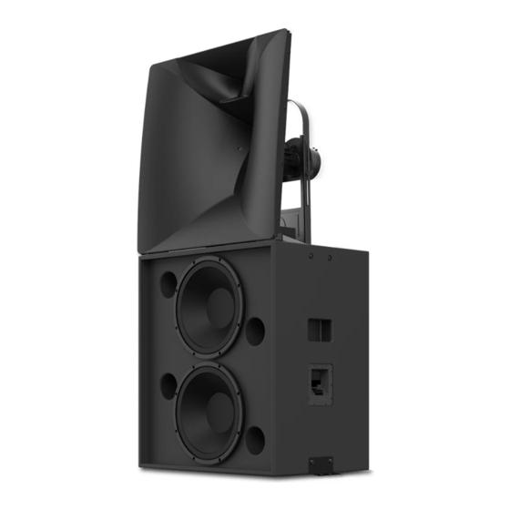
Figure 3: Dolby asymmetrical horn coverage 2.3 CS136LF key features and benefits System 131 utilizes one CS136LF unit to produce the low frequencies and low/mid frequencies. Figure 4: CS136LF • Contains two 15-inch woofers that can be driven in parallel, or driven individually to maximize available amplifier power. -
Page 10: Selecting The Wire For The System 131
It is important that you select the correct wire gauge for the System 131. Typically, no more than 0.5 dB (or 11%) of power should be lost in the cabling. The System 131 input plates accept an American Wire Gauge (AWG) of 18 AWG to 6 AWG (1 mm to 16 mm ). -
Page 11: Installing System 131 In A Typical Auditorium
Figure 6: System 131 acoustic center System 131 is designed to be placed as close to the screen surface as possible with a minimum distance of 5-7 cm. This minimizes high-frequency reflections (screen loss) and reduces airflow disturbances on the screen surface. - Page 12 Figure 7: System 131 screen planes .GLL format files for software simulation modeling There are .GLL files for the CS131MH and CS136LF that you can use to simulate System 131 in acoustical simulation software. You can download the .GLL files at https//:www.dolby.com/us/en/professional/...
-
Page 13: Additional Information
System 131 is switchable between triamplifier mode or biamplifier mode. We recommend triamplifier mode for maximum performance. • Amplifier selection is aided by additional data, as specified in the System 131 and system components specifications. (See the link at the end of this section.) •... -
Page 14: Assembling System 131
(for example, mounting by drilling holes into the speaker system) will render the product warranty null and void. The following sections provide instructions on how to assemble and install System 131. • Assembling and installing System 131 •... -
Page 15: Assembling And Installing System 131
Securing the low-frequency cabinet Procedure 1. Once you determine the proper placement of the system relative to the screen, secure System 131 to the building structure, using a platform on the screen frame. For this purpose, we recommend the use of the BKT.FLR brackets or equivalent brackets not. - Page 16 (for example, mounting by drilling holes into the speaker system) will render the product warranty null and void. Attention: The System 131 was designed to be placed as close to the screen as possible, within 5-7 cm. When aiming the system, angling of the CS136MH may require that the speaker system be...
- Page 17 Loctite 243). Do not fully tighten the bolts until aiming is completed. Figure 10: Mount mid/high speaker to low-frequency cabinet Figure 11: CS131MH overhead view Mounting screws (under horn) Tracks allowing horn to be rotated Dolby Speaker System 131 Owner's Manual Issue 1 Part number: 8800300 1 January 2022...
-
Page 18: Aiming System 131
Assembling System 131 3.2 Aiming System 131 It is important to aim System 131 for precise sound distribution. About this task Illuminate a typical aiming point that is located two-thirds back and centered in the auditorium seating area using the laser-pointer placement shelf. To aim the system, you can use any type of laser pointer, as long as the beam shines through the hole in the CS131MH horn and the laser body is parallel to the shelf. - Page 19 Aiming System 131 Procedure 1. Once the System 131 is assembled, adjust the horizontal axis of the speaker by rotating the CS131MH on the cabinet. The angle adjustment range is ±20 degrees from the center, as shown on the provided decal stickers.
-
Page 20: Connecting Electrical Components
Required tool: Wire stripper Caution: Turn off all amplifiers when connecting loudspeaker wiring. The System 131 connectors accept an American Wire Gauge (AWG) of 18 AWG to 6 AWG (1 mm to 16 mm Typically, a wire gauge of 16 AWG to 12 AWG is recommended (1.5 mm... - Page 21 Connecting electrical components Basic information is provided regarding System 131 input plates, choosing between the two modes of operation, and installing the wiring. Detailed information regarding speaker operating modes is also provided. Connecting and configuring the CS131MH At the base of the CS131MH, there is a small box that contains an input plate with wiring inputs, flip card, and a passive crossover, as shown in the following figure.
- Page 22 1 for the mid-frequency driver (the larger icon), and position 2 for the high-frequency driver (the smaller icon), as shown in the following figure. Figure 20: CS131MH input plate with flip card in active mode Dolby Speaker System 131 Owner's Manual Issue 1 Part number: 8800300 1 January 2022...
- Page 23 Icon 1 represents the top driver in the cabinet, and icon 2 represents the bottom driver in the cabinet. There is no crossover in the CS136LF. Dolby Speaker System 131 Owner's Manual Issue 1 Part number: 8800300...
- Page 24 You set the operating mode for each system component using its flip card. Remove the flip card by pulling it straight out and then reinsert it with the arrow pointing to the desired operation mode. Dolby Speaker System 131 Owner's Manual Issue 1 Part number: 8800300...
- Page 25 In this mode, the CS131MH mid- and high-frequency drivers are processed and amplified independently. The CS136LF covers some mid frequencies in addition to low frequencies, as shown in the following figure. Figure 24: System 131 triamplifier configuration This CS131MH biamplifier configuration provides two 8 ohm loads that are driven by independent amplifier channels with independent DSP processing for each channel.
- Page 26 Assembling System 131 The biamplifier configuration connects to two channels of amplification. Figure 26: System 131 biamplifier configuration The mid/high passive configuration is an 8 ohm load to a single amplifier channel. Figure 27: Mid/high passive configuration 1 1 1 1 1 1...
- Page 27 Connecting electrical components The low-frequency parallel configuration is a 4 ohm load to a single amplifier channel Figure 28: Low-frequency parallel-wiring configuration Dolby Speaker System 131 Owner's Manual Issue 1 Part number: 8800300 1 January 2022...
- Page 28 50 percent for the respective amplifier channel. In this configuration, you need to point the flip card to the right. Figure 29: Low-frequency alternative cabinet configuration Dolby Speaker System 131 Owner's Manual Issue 1 Part number: 8800300 1 January 2022...
-
Page 29: Dolby Speaker System 131 And System Components Specifications
Dolby Speaker System 131 and system components specifications Dolby Speaker System 131 and system components specifications The specifications for Dolby Speaker System 131 and its system components are available. The list below is an outline of this chapter: • Dolby Speaker System 131 specifications •... -
Page 30: Dolby Speaker System 131 Specifications
Dolby Speaker System 131 and system components specifications 4.1 Dolby Speaker System 131 specifications These are the specifications for Dolby Speaker System 131. Table 1: Dolby Speaker System 131 specifications Specification Technical data Notes Frequency range 31 Hz to 20 kHz +3 dB/-6 dB in half-space conditions using required processing. -
Page 31: Cs131Mh Specifications
CS131MH specifications Table 1: Dolby Speaker System 131 specifications (continued) Specification Technical data Notes CS136LF power handling 1,400 watts @ 74.8 V 12 dB crest pink noise for two hours with required HPF and LPF, based on AES2-2012 standard, calculated power based on rated impedance. - Page 32 Dolby Speaker System 131 and system components specifications Table 2: CS131MH specifications (continued) Specification Technical data Notes Passive mode power draw 123 W Measured average power over five seconds at the rated V using 12 dB crest IEC 60268-1 noise with required HPF and LPF.
-
Page 33: Cs136Lf Specifications
12 dB crest pink noise with required HPF and LPF CS136LF weight 72.7 kg (160 lb) Note: These specifications provide typical values and do not represent absolute limits. Dolby Speaker System 131 Owner's Manual Issue 1 Part number: 8800300 1 January 2022... -
Page 34: Dolby Speaker System Dimensions
Dolby Speaker System 131 and system components specifications 4.4 Dolby Speaker System dimensions Dolby Speaker System 131 Owner's Manual Issue 1 Part number: 8800300 1 January 2022... -
Page 35: Dolby Speaker System 131 Digital Signal Processing Requirements
Dolby Speaker System 131 digital signal processing requirements Dolby Speaker System 131 digital signal processing requirements The tables in this chapter show the System 131 digital signal processing requirements for the different modes of operation. The list below is an outline of this chapter: •... -
Page 36: System 131 Triamplifier Mode
Dolby Speaker System 131 digital signal processing requirements 5.1 System 131 triamplifier mode There are a variety of System 131 triamplifier mode digital signal processing requirements. Table 4: CS131MH High-frequency highpass and lowpass filtration, gain, and delay requirements Highpass filter... -
Page 37: System 131 Biamplifier Mode
Peak stop in Vpk 74.8 149.6 5.2 System 131 biamplifier mode There are a variety of System 131 biamplifier mode digital signal processing requirements. Table 13: CS131MH mid/highfrequency highpass and lowpass filtration, gain, and delay requirements Highpass filter Lowpass filter... - Page 38 Dolby Speaker System 131 digital signal processing requirements Note: Overall gain is for an anechoic flat response, whereas room effects are visible in acoustic measurements. The alternative Cinema preset gain takes into account typical room and screen effects to more closely generate an acoustic measurement x-curve shape with less user adjustment required.
- Page 39 System 131 biamplifier mode Table 18: CS136LF limiter requirements RMS limiting in Vrms Attack time in ms Release time in ms Peak stop in Vpk 74.8 149.6 Dolby Speaker System 131 Owner's Manual Issue 1 Part number: 8800300 1 January 2022...
-
Page 40: Setting System Limiters
7. While pink noise is playing at the rated V (or there is heavy amplifier clipping), turn down the threshold on the root mean square (RMS) limiter block until the measured V goes down slightly. Dolby Speaker System 131 Owner's Manual Issue 1 Part number: 8800300 1 January 2022... - Page 41 It is also acceptable to copy the limiter settings to identical channels if the auditorium equalization (EQ) and/or gain structure is different before the limiter in the signal path. Dolby Speaker System 131 Owner's Manual Issue 1 Part number: 8800300 1 January 2022...
-
Page 42: Documentation Revision History
Documentation revision history Documentation revision history The documentation revision history lists the date, issue number, and description of all publications of Dolby Speaker System 131 Owner's Manual . Date Issue Description 1 January 2022 Issue 1 Initial release Dolby Speaker System 131 Owner's Manual... - Page 43 Dolby Laboratories, Inc. 1275 Market Street, San Francisco, CA 94103-1410 USA. 2022 Dolby Laboratories. All rights reserved. Dolby and the double-D symbol are registered trademarks of Dolby Laboratories. © All other trademarks remain the property of their respective owners.
Need help?
Do you have a question about the 131 and is the answer not in the manual?
Questions and answers