
Subscribe to Our Youtube Channel
Related Manuals for Dolby Laboratories 136


Summary of Contents for Dolby Laboratories 136
- Page 1 Dolby Speaker System 136 Owner’s Manual 16 December 2020 Issue 1: Part number 8800255...
- Page 2 THIS DOCUMENTATION APPLIES TO MODEL: CID1024 and MODEL: CID1025. Limited warranty and warranty exclusions THE LIMITED WARRANTY AND WARRANTY EXCLUSIONS MAY BE FOUND AT THE FOLLOWING URL: https:// www.dolby.com/us/en/about/warranty-and-maintenance-policies.html Dolby Speaker System 136 Owner’s Manual Issue 1: Part number 8800255 16 December 2020...
-
Page 3: Table Of Contents
3.3 Aiming System 136............................19 3.4 Connecting electrical components ......................22 4 System 136 and system components specifications................ 30 5 System 136 digital signal processing requirements.................35 6 Setting system limiters.........................37 Dolby Speaker System 136 Owner’s Manual Issue 1: Part number 8800255 16 December 2020... -
Page 4: Important Safety And Regulatory Information
Installer assumes all responsibility for the appropriate use of Dolby supplied rigging hardware and follows at a minimum all applicable laws, rules, and regulations in force for each venue. Dolby Speaker System 136 Owner’s Manual Issue 1: Part number 8800255 16 December 2020... - Page 5 BKT.136 tie (coupling) plates (included with CS136MH) are used to connect the two CS136LF speakers together to prevent movement or shifting of the cabinets due to vibration from high levels of sound.
- Page 6 Waste Electrical and Electronic Equipment (WEEE) and product disposal go to http:// www.dolby.com/us/en/about/environmental-commitment.html. Russian environmental regulations and compliance This product complies with Russian EAC RoHS requirements. Dolby Speaker System 136 Owner’s Manual Issue 1: Part number 8800255 16 December 2020...
-
Page 7: Introduction To Dolby Speaker System 136
Introduction to Dolby Speaker System 136 The Dolby Speaker System 136 is designed to meet the needs of a high-performance screen speaker in a large Dolby Atmos or premium large format (PLF) cinema. System 136 delivers consistent audio coverage and uniform volume shading for every seat in the venue up to approximately 165 feet (50.3 meters) in depth. -
Page 8: About This Documentation
2.2 CS136MH key features and benefits Dolby Speaker System 136 uses one CS136MH unit, which reproduces mid- and high-frequency audio using a dual-entrant horn (two drivers in the same horn structure) that enables close proximity of the mid- and high- frequency drivers in the vertical plane. -
Page 9: Cs136Lf Key Features And Benefits
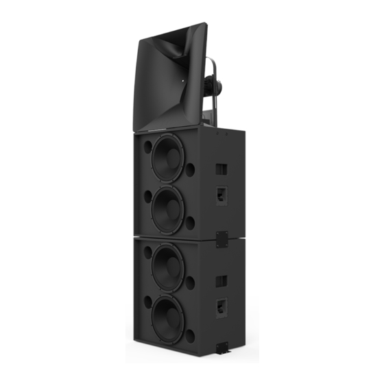
Figure 3: Dolby asymmetrical horn coverage 2.3 CS136LF key features and benefits Dolby Speaker System 136 utilizes two CS136LF units to produce the low frequencies and low/mid frequencies. Each cabinet receives differently processed audio. Figure 4: CS136LF two units stacked Dolby Speaker System 136 Owner’s Manual Issue 1: Part number 8800255... -
Page 10: Selecting The Wire
This section can assist you in selecting the correct wire gauge. Typically, no more than 0.5 dB ( or 11%) of power should be lost in the cabling. The System 136 input plates accept an American wire gauge (AWG) of 18 AWG to 6 AWG. - Page 11 Contacting Dolby Access documentation Visit https://customer.dolby.com. Submit feedback about this documentation Send an email to documentation@dolby.com. Dolby Speaker System 136 Owner’s Manual Issue 1: Part number 8800255 16 December 2020...
-
Page 12: Assembling System 136
Assembling System 136 Assembling System 136 The following sections provide instructions on how to assemble and install System 136. • Installing System 136 in a typical auditorium • Assembling and Installing System 136 • Aiming System 136 • Connecting electrical components Dolby Speaker System 136 Owner’s Manual Issue 1: Part number 8800255... -
Page 13: Installing System 136 In A Typical Auditorium
Installing System 136 in a typical auditorium 3.1 Installing System 136 in a typical auditorium In a typical auditorium, System 136 is installed behind the screen, with the acoustic center of the speaker located two-thirds of the distance from the bottom of the screen. - Page 14 Assembling System 136 System 136 is designed to be placed as close to the screen surface as possible within 5-7 cm. When aiming the system, angling of the CS136MH may require that the entire system be set back from the screen to accommodate proper tilting and aiming.
- Page 15 • CS136LF for Screen Channel System 136 To create the System 136 screen channel. The loudspeaker entry point into the simulation is at the bottom of the stack. For correct simulation, place the LF stack height entry point (z axis) at the platform height in the auditorium.
-
Page 16: Assembling And Installing System 136
System 136 was designed to be placed as close to the screen as possible, within 5-7 cm. When aiming the system, angling of the CS136MH may require that the entire system be set back from the screen to accommodate proper tilting and aiming. - Page 17 BKT.136 kit. Figure 10: Mount top low-frequency cabinet to bottom low-frequency cabinet Rubber feet on top cabinet set into recesses on top panel of bottom cabinet Dolby Speaker System 136 Owner’s Manual Issue 1: Part number 8800255 16 December 2020...
- Page 18 Assembling System 136 3. Reinstall the bolts with the BKT.136 coupling plates, and retighten the M10 bolts to 12 newton meters (Nm) [8.9 ft-lb, 106 in-lb]. We recommend using a serviceable thread-locking compound (for example, Loctite 243) to prevent the screws from vibrating out of position. All supplied fasteners must be in place to avoid air leaks in the speaker enclosure.
-
Page 19: Aiming System 136
Figure 14: Aiming for the reference listening position overhead view Dolby Speaker System 136 Owner’s Manual Issue 1: Part number 8800255 16 December 2020... - Page 20 Assembling System 136 Figure 15: Placing the laser Laser pointer placement location Procedure 1. After assembling System 136, adjust the speaker horizontal axis by rotating the CS136MH on the cabinet. Figure 16: Adjust CS136MH horizontal axis Mounting screws (Under horn) Tracks allowing horn to be rotated 2.
- Page 21 8. After aiming is completed, install decal stickers on the mid-range horn to hide the two laser-pointer openings. Figure 19: Hide two openings with decals Decal placement for concealing aiming point aperture in midrange horn Dolby Speaker System 136 Owner’s Manual Issue 1: Part number 8800255 16 December 2020...
-
Page 22: Connecting Electrical Components
Required tool: Wire stripper CAUTION: Turn off all amplifiers when connecting loudspeaker wiring. System 136 connectors accept an American wire gauge (AWG) of 18 AWG to 6 AWG. Typically, a wire gauge of 16 AWG to 12 AWG is recommended. - Page 23 TO PREVENT INJURY, THIS APPARATUS MUST BE PASSIVE SECURELY ATTACHED TO THE FLOOR / WALL IN ACTIVE ACCORDANCE WITH THE INSTALLATION INSTRUCTIONS H H F F + + + + Terminal tabs Dolby Speaker System 136 Owner’s Manual Issue 1: Part number 8800255 16 December 2020...
- Page 24 3. Insert the wire fully into the hole. 4. Release the terminal tab. The spring mount clamps the wire securely. 5. Inspect the terminal for any stray wire strands. Dolby Speaker System 136 Owner’s Manual Issue 1: Part number 8800255 16 December 2020...
- Page 25 TO PREVENT INJURY, THIS APPARATUS MUST BE SECURELY ATTACHED TO THE FLOOR / WALL IN ACCORDANCE WITH THE INSTALLATION INSTRUCTIONS L L F F Terminal tabs Dolby Speaker System 136 Owner’s Manual Issue 1: Part number 8800255 16 December 2020...
- Page 26 The bottom CS136LF is exclusively for low- frequency output. Figure 26: System 136 quad-amplifier configuration High frequency Mid frequency Mid/low frequency Low frequency 28 hz Frequency 20 khz Dolby Speaker System 136 Owner’s Manual Issue 1: Part number 8800255 16 December 2020...
- Page 27 The tri-amplifier configuration connects to three channels of amplification. Figure 28: System 136 Tri-amplifier configuration High frequency Mid frequency Mid/low frequency Low frequency 28 hz Frequency 28 khz Dolby Speaker System 136 Owner’s Manual Issue 1: Part number 8800255 16 December 2020...
- Page 28 Figure 29: Mid/high passive configuration 1 1 1 1 1 1 The low-frequency parallel configuration is a 4-ohm load to a single amplifier channel. Figure 30: Low-frequency parallel-wiring configuration Dolby Speaker System 136 Owner’s Manual Issue 1: Part number 8800255 16 December 2020...
- Page 29 50 percent for the respective amplifier channel. In this configuration, you need to point the flip card to the right. Figure 31: Low-frequency alternate-cabinet configuration Dolby Speaker System 136 Owner’s Manual Issue 1: Part number 8800255 16 December 2020...
-
Page 30: System 136 And System Components Specifications
Measured with 12 dB crest pink noise 1 watt @ 2 V in half-space conditions with required HPF and LPF respectively, for top and bottom cabinets. Dolby Speaker System 136 Owner’s Manual Issue 1: Part number 8800255 16 December 2020... - Page 31 MF used required HPF and LPF. HF used required HPF and a 48 dB BW LPF at the rated frequency range of the system. Dolby Speaker System 136 Owner’s Manual Issue 1: Part number 8800255 16 December 2020...
- Page 32 HPF and LPF. HF used required HPF and a 48 dB BW LPF at the rated frequency range of the system. Total peak SPL is presented as a noncoherent summation. Dolby Speaker System 136 Owner’s Manual Issue 1: Part number 8800255 16 December 2020...
- Page 33 900 W @ 60 V 12 dB crest pink noise for 2 hours with required HPF and LPF, based on AES2-2012 standard, calculated power based on rated impedance. Dolby Speaker System 136 Owner’s Manual Issue 1: Part number 8800255 16 December 2020...
- Page 34 2266 2493 Acoustic center 66.72 1695 33.46 29.87 20.34 CS136LF cabinet only 30.46 Inches [ ] and Millimeters Bolt heads with floor plates and/or tie plates Dolby Speaker System 136 Owner’s Manual Issue 1: Part number 8800255 16 December 2020...
-
Page 35: System 136 Digital Signal Processing Requirements
System 136 digital signal processing requirements These tables show the System 136 digital signal processing requirements for the different modes of operation. Note: *There are two principal implementations for parametric EQ filters in DSP processors. You need to select either the Constant Q or Constant Bandwidth mode in your DSP user interface (UI). - Page 36 RMS limiting in V Attack in ms Release in ms Peak stop in Vpk 63.3 126.6 Note: These specifications provide typical values and do not represent absolute limits. Dolby Speaker System 136 Owner’s Manual Issue 1: Part number 8800255 16 December 2020...
-
Page 37: Setting System Limiters
HPF 1 kHz to 1.99 kHz: attack 0.5 ms, release 8 ms • HPF >2k Hz: attack 0.3 ms, release 4.8 ms 5. Mute all outputs into the system, except for the output you are setting. Dolby Speaker System 136 Owner’s Manual Issue 1: Part number 8800255 16 December 2020... - Page 38 (including any amplifier front-panel volume controls). It is also acceptable to copy the limiter settings to identical channels if the auditorium equalization (EQ) and/or gain structure is different before the limiter in the signal path. Dolby Speaker System 136 Owner’s Manual Issue 1: Part number 8800255 16 December 2020...
Need help?
Do you have a question about the 136 and is the answer not in the manual?
Questions and answers