
Related Manuals for CPS DPA03-800V/US


Summary of Contents for CPS DPA03-800V/US
- Page 1 Installation and Operation Manual for CPS DPA03-800V/US AC Combiner CHINT POWER SYSTEMS AMERICA CO., LTD. Rev 2.0 Nov. 30, 2021...
-
Page 2: Table Of Contents
Table of Contents Table of Contents Preface ..................4 Safety ..................5 Symbols and meanings in this document .......... 5 Markings and meanings on the device ..........5 Safety precautions of operating the Combiner ........6 General Introduction .............. 7 Overview of Grid-tied PV system ............ - Page 3 Table of Contents 5.2.1 Regular inspection ..............23 5.2.2 Fuse replacement ..............23 Technical Data ..............24 Quality Assurance ..............25 Warranty period ................25 Exemption of liability ................ 25 Warranty clause ................25 Contact Information ............. 26 Appendix ................27 Appendix A: Figure list ..............
-
Page 4: Preface
Copyrights CPS reserves all rights in this manual. Any reproduction, disclosure or copy in whole or in part is forbidden without prior written authorization. CPS doesn’t accept any responsibilities whatsoever for potential errors or possible lack of information in this document. -
Page 5: Safety
Safety Please read this user manual carefully before the installation and operation of this Combiner. CPS reserves the right to refuse warranty claims for equipment damages if users fail to install the equipment according to the instructions in this manual. -
Page 6: Safety Precautions Of Operating The Combiner
Safety RoHS SYMBOL In accordance with 2011/65/EU regulations, the inverter imposes restrictions on the use of specific hazardous substances in electrical and electronic equipment. TUV Certification This inverter has passed TUV Certification. Safety precautions of operating the Combiner Symbol Meanings DANGER! ... -
Page 7: General Introduction
This AC Combiner shall be used in combination with the new generation of CPS SCH275KTL-DO/US-800 series string PV inverter developed by CPS. For the position and function of the AC Combiner in the Grid-tied PV system, refer to Figure 2-1. -
Page 8: Features Of Ac Combiner
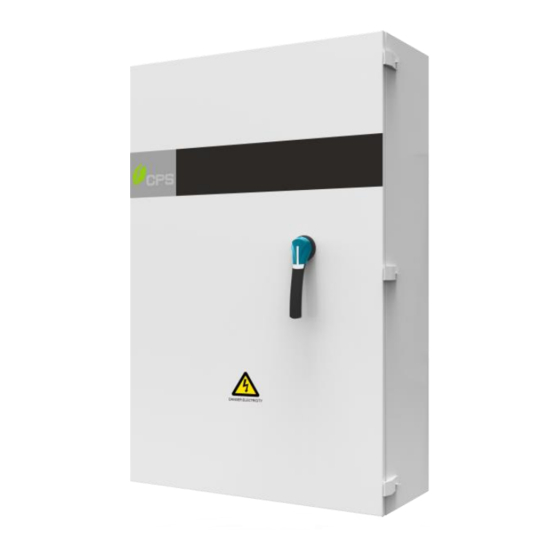
General Introduction Figure 2-3 Product Appearance Item No. Component Name Hasp locks (refer to Open the door) Operation handle Hooks Handrails Table 2-1 Component Name Features of AC Combiner High reliability High-voltage switch equipped with TYPE3R outdoor operation handle, which is designed especially for PV system; Door cannot be opened once the machine is powered on;... -
Page 9: Nameplate
General Introduction Nameplate The device nameplate contains important information of the device, including model number, serial number and detailed parameters, etc. You can find the nameplate of Combiner on the left side of its enclosure, as shown in Figure 2-4. Figure 2-4 Nameplate 2.4.1 Model No. -
Page 10: Serial No
General Introduction 2.4.2 Serial No. The serial No. can be found out at the bottom left corner in the back side of the door, as shown in Figure 2-6 (for reference). Figure 2-6 Serial No. The serial no is a list of 11 numbers and each number has its special meanings, the bar code is made up of 128 codes, as shown below (just for reference). -
Page 11: Storage Requirements
General Introduction Storage requirements Close the door tightly, to avoid from opening accidentally. Storage space shall be clean and dried and be free from dust or moisture. The temperature of the storage space shall be kept between -40℃ and +70℃... -
Page 12: Mechanical Installation
Mechanical Installation Mechanical Installation Unpacking for Inspection Check the product for any obvious damages or if the items in the delivery list are complete before performing installation. Contact your supplier immediately if any problem is found. The delivery list of the Combiner is as below: Images Accessories QTY (pcs) -
Page 13: Foundation Requirements
Mechanical Installation 3.2.2 Foundation requirements Before installing the AC Combiner, concrete platforms and trenches shall be constructed. The requirements for constructing foundation are as follows: Foundation dimensions shall meet the requirements for Combiner installation and bearing capacity. The level error between the foundation and contact surface shall be less than 5mm. - Page 14 Mechanical Installation Install the AC Combiner on the integrated mounting bracket as shown below: Position one fixed bracket (2) onto one side of the mounting bracket (3) and fasten it with one M4*12 securing screw (1) via screwdriver as shown. Figure 3-1 Position one fixed bracket Hoist the bottom of the Combiner till all its hooks (4) are aligned with the mounting bracket (3) and hang them onto the mounting brackets...
- Page 15 Mechanical Installation Slide the side plate of Combiner along the mounting bracket, until it stays closely with the fixed bracket. Figure 3-3 Slide the Combiner Fasten the fixed bracket onto the hooks of the Combiner by screwing another two M4*12 securing screws into the holes of the fixed bracket. Then fasten another fixed bracket onto the other side of the mounting bracket to avoid the accidental movement of the Combiner.
-
Page 16: Open And Close The Door
Mechanical Installation Open and close the door WARNING! Make sure the power supply is disconnected before opening and closing the Combiner. In order to guarantee the protection performance of the Combiner, three hasp locks with lock holes are provided, refer to the figure 3-5. After completing the operation, all the hasp locks (1) shall be locked, to avoid accidental turning the operation handle (2) of the disconnect switch and opening of the Combiner further, thus causing the risk of electric shock! -
Page 17: Close The Door
Mechanical Installation Perform the following steps to open the Combiner: Turn the operation handle of the disconnect switch to the opened position. Unlock the padlock and take it off from the lock hole (3). Lift the dovetail (4) of the hasp lock and separate the hasp (2) from its staple (1);... -
Page 18: Electrical Connection
Electrical Connection Electrical Connection WARNING! Be careful of high AC voltage! Check all the input and output cables or terminals to ensure there’s no voltage before electrical connection to avoid electric shock! CAUTION! Connect the cables following strictly the polarities marked on the device to avoid short circuit hazards. -
Page 19: Internal Wiring Terminals And Cable Specification
Electrical Connection Internal wiring terminals and cable specification Figure 4-2 Internal wiring terminals Name Cable Specification GND terminal (Copper platoon) Max.300MCM Cu/AL Out. terminal (Copper platoon) Max. 2 to 4 conductors 750MCM Cu/AL Disconnect switch SIRCO 3X800VAC series; Outdoor operation handle; Conform to UL98C standard. -
Page 20: Wiring
Electrical Connection Wiring 4.4.1 Cable connection Figure 4-3 Cable connection Perform cable connection according to the following steps: Grounding Connect its grounding cable to the GND terminal. Tighten the GND terminal with M12 securing screws, flat washers and spring washers. Input terminal Connect its input terminals to the output terminal of the inverter. -
Page 21: Create Conduit Entry Holes
Electrical Connection 4.4.2 Create conduit entry holes There is a removable plate at the bottom of the enclosure for customers to create the conduit entry holes themselves. Perform as the following steps: Remove the bottom plate from the enclosure by loosening the securing screws with a screwdriver. -
Page 22: Operation And Maintenance
After the inverter works normally, see the branch currents via the monitoring software. 5.1.2 Shut down Turn the inverter off by using the CPS connect Pro APP. Turn off the DC switches at the inverter. Turn the operation handle of the disconnect switch to the opened position. -
Page 23: Maintenance
Operation and Maintenance Maintenance WARNING! Be careful of the live parts of the input and output sides when checking or maintaining the device to avoid electric shock. 5.2.1 Regular inspection To keep the device working normally for a long time, it is necessary to check its working status regularly. -
Page 24: Technical Data
Technical Data Technical Data Parameters Values Model CPS DPA03-800V/US Number of Input Circuits Input Mode By inverter Rated Voltage 800 VAC Rated Frequency 50/60 Hz Rated Input Current 3x198.5 A Specification of Input Inverter 275 KW 800 VAC 250-500kcmil CU or 350-500kcmil AL... -
Page 25: Quality Assurance
Unexpected disasters or force majeure. Warranty clause CPS will repair the faulty device or replace it with new ones during the warranty period; The non-conformance substitutes should be returned to CPS;... -
Page 26: Contact Information
Contact Information Contact Information Please do not hesitate to contact us if you have any questions regarding CPS DBA03-800V/US AC Combiner. We are glad to provide the best service for you. CHINT POWER SYSTEMS AMERICA CO., LTD. Address: 1297 N Plano Rd Richardson Texas 75081... -
Page 27: Appendix
Appendix Appendix Appendix A: Figure list Figure 2-1 Grid-tied PV system ..............7 Figure 2-2 Product Dimension ..............7 Figure 2-3 Product Appearance ..............8 Figure 2-4 Nameplate ................9 Figure 2-5 Naming convention of the model ..........9 Figure 2-6 Serial No................10 Figure 2-7 Naming convention of the serial no........10 Figure 2-8 Temperature and relative humidity of the storage space ..
Need help?
Do you have a question about the DPA03-800V/US and is the answer not in the manual?
Questions and answers