
Related Manuals for NPM FMC 32

Summary of Contents for NPM FMC 32
- Page 1 FMC 32 Hardware User's Manual YA7174-0E Compact controller with integrated driver FMC32 Hardware User's Manual ...
-
Page 2: Table Of Contents
YA7174-0E Table of Contents 1. Preface................................2 2. Product Warranty ............................. 3 2-1. In the case of purchase from a supplier other than NPM ................. 3 2-2. Warranty period ............................. 3 2-3. Warranty scope ............................3 3. Outline................................4 4. -
Page 3: Preface
PCD2112 thoroughly. A CPU is equipped with the FMC 32. You can repeat the execution sequence program that is written to the FMC 32 automatically. If you use a motor and a driver additionally, you can confirm operation in more detail. -
Page 4: Product Warranty
Note 1) Products exported outside of Japan are not covered by this warranty. Note 2) Only if the product with defects is carried to the specific place to repair, NPM will repair the product and we will not provide on-site repair. -
Page 5: Outline
To control operation patterns, Pulse control LSI PCD 2112 for Serial Bus Control is equipped. The FMC 32 contains a 2 phase stepper motor driver (NP3775E3) to drive bipolar stepper motor. Through the use of a switch, the FMC32 can output pulses to external drivers. -
Page 6: Specifications
FMC32 Hardware User's Manual YA7174-0E 5. Specifications Product name:FMC32, a compact controller with built-in driver Input voltage[VM]/Maximum current DC +24V ±10% / 1.2A [A] Model NP3775E3 Control method Bipolar constant current operation 2 phase excitation(FULL)/1-2 phase excitation(HALF) Excitation method Selectable by switching SW1 to 4 0.5 A/phase [MAX], changeable by using VR Current-down function after stopped (approximately 50% of... - Page 7 FMC32 Hardware User's Manual YA7174-0E Model PCD2112 Reference clock 9.8304 MHz Control method 4-wire serial bus interface Output pulse 2.4 Mpps max frequency Number of 0 to 268,435,455 (28 bits) positioning pulses Operation pattern Available to save up to 32 operation patterns to the nonvolatile memory. Execution sequence Available to save up to 256 steps of the execution sequence program to program...
-
Page 8: Function Description
FMC32 Hardware User's Manual YA7174-0E 6. Function description 6-1. Terminal functions For DC +12V power input Terminal Terminal Signal description Name 1 DC +24V power input Open DC +24V power GND For connection with a motor Motor phase Signal description Terminal Name Terminal No. - Page 9 FMC32 Hardware User's Manual YA7174-0E External interface Terminal Terminal Signal explanation name External power input for photocouplers of MON, STA, +EL, -EL, ORG and SD. The anode side of the photocouplers for the above signals is pulled up to EXP with 1KΩ. EXP input range : DC4.5V to 7V Excitation ON/OFF Input Photocoupler ON : Excitation ON Photocoupler OFF : Excitation OFF...
-
Page 10: Sw1 Settings
FMC32 Hardware User's Manual YA7174-0E For connection with SPI Terminal name Terminal No. Signal description SPI CS signal input MODE MODE signal to PCD2112 Note 1 SPI clock SPI DI SPI DO Note 1: When connecting with PUSB-3503 (USB-SPI conversion unit), MODE signal is connected to GND. The mode become the PC control one. -
Page 11: Current Adjustment
FMC32 Hardware User's Manual YA7174-0E 6-4 Current adjustment Procedure of Current Adjustment is as follows. Connect CN1 to DC+24V, CN2 to a bipolar stepper motor, a digital volt meter between CP2 and CPG, and CN4 to PUSB-3503. Connect PUSB-3503 to USB port of PC. First of all, turn the VR1 to the maximum on the scale in the CCW direction and then make the motor current value minimum. -
Page 12: Connection Example Of Input/Output Interface
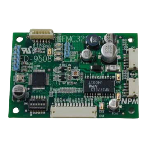
FMC32 Hardware User's Manual YA7174-0E 7. Connection example of input/output interface External power Controller FMC32 Input signal TLP280 1KΩ MON,STA,+EL -EL,ORG,SD Output signal END,MOT PLS,DIR 74LS07 TLP280 8. External diameters and component layout ... -
Page 13: Circuit Block Diagram
FMC32 Hardware User's Manual YA7174-0/0 9. Circuit block diagram [ Circuit block diagram ] Vdd Vdd Vdd Vdd [CN4] CS:1 ○ EEPROM MODE:2 ○ CS_N SCK:3 ○ GND:4 ○ SDI:5 ○ [CN1] SDO:6 ○ ○... - Page 14 The descriptions in this manual may be changed without prior notice to CAUTION improve performance or quality. Nippon Pulse Motor Co., Ltd. Head Office: No.16-13, 2-chome, Hongo, Bunkyo-ku, Tokyo, 113-0033, Japan TEL: 81-3-3813-8841 FAX: 81-3-3813-8665 Web: http://www.pulsemotor.com E-mail: int-l@npm.co.jp Issued in September 2011 - - ...
Need help?
Do you have a question about the FMC 32 and is the answer not in the manual?
Questions and answers