Table of Contents
Advertisement
Quick Links
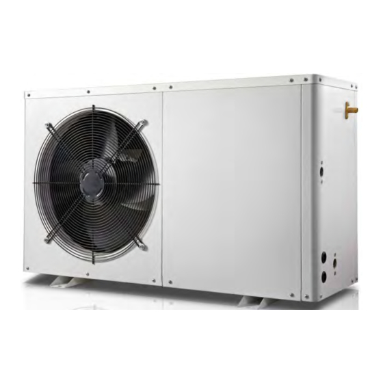
Air to Water Heat Pump
Installation & Operation Manual
Model Number : SSD-0360410A
S S D -0 5 4 0410A
SSD-0900410A
S S D - 0132410A
A Guide to the installation and operation of SunScan SunSmart Air to water Heat pumps.
Please read this manual carefully before installing and operating the Heat pump
Retain this document for future referencece.
Advertisement
Table of Contents

Related Manuals for SUNSCAN SunSmart SSD-0360410A

Summary of Contents for SUNSCAN SunSmart SSD-0360410A
- Page 1 S S D -0 5 4 0410A SSD-0900410A S S D - 0132410A A Guide to the installation and operation of SunScan SunSmart Air to water Heat pumps. Please read this manual carefully before installing and operating the Heat pump Retain this document for future referencece.
- Page 3 SunScan range of heat pumps, please note that this manual is specific to the product/s listed or described on the cover page. If after reading this manual any aspect of the installation process remains unclear contact a SunScan representative prior to installation.
- Page 4 This manual must be read thoroughly and understood WARNING before undertaking to install any of the SunScan range of heat pumps. Failure to follow safety warnings and instructions may result in severe injury, death, or property damage. Codes and Standards...
- Page 5 What's in the box? Name Qty. Installation &Operation Manual Wire-controller Wire-controller s ensor wire Wire controller box & pad (plastic) Power cable (selected models) Drain-pipe Drain-pipe connector Rubber shock absorber Heat Pump Unit - 3 -...
-
Page 6: Table Of Contents
Please read the manual carefully before operation and keep it for future reference. Content General Safety ..................5 How H eat Pump s Work..............8 Install ing The Unit ................9 Install ing The Water Pipes.............. 10 Instal ling Electrical Components ...........12 Operating Instructions... -
Page 7: General Safety
General Safety Range of application: 1. Power supply: 230V/1N~50Hz. 2. Environment temperature: -7°C〜43°C : NOTICE The heat pump has a anti-freezing operation. In winter when the ambient is below 0℃, the unit will start automatically to keep water from freezing, this protects the unit and water piping system. - Page 8 Use a dedicated socket outlet / circuit for this unit. Keep the unit away from other home appliance or heat sources, this prevents any possible magnetic interferance and ensures the unit'sperformance. Do not touch the power plug or any electrical components with wet hands.
- Page 9 Do not touch the air outlet grill when fan motor is running Always select the correct fuse or breaker. Steel wire or copper wire cannot be used as a substitute for fuse or breaker. Please ensure the power supply is switched off before any maintenance / cleaning works.
-
Page 10: How H Eat Pump S Work
How h eat Pump s work 1. Heat pump process Heat pumps transfer heat by circulating refrigerant through a cycle of evaporation and condensation. A compressor pumps the refrigerant between two heat exchanger coils. In one coil, the refrigerant is evaporated at low pressure and absorbs heat from its surroundings. -
Page 11: Install Ing The Unit
Install ing The Unit 1. Installation check ● Ensure the model number, name etc corresponds to this manual to avoid incorrect installation. ● Ensure adequete space for installation and maintenance. ● Ensure there are no obstructions to the air inlet and outlet. ●... -
Page 12: Install Ing The Water Pipes
3. Hoisting ● Use four or more soft lifting belts to move the unit . ● Use protective plates on the surface of the unit when moving, this will avoid scratches and deformation. ● Check that the mounting structure is suitable before hoisting the unit. ●... - Page 13 2. Instruction (1) Water pipe installation diagram Figure 5 Diagram - 11 -...
-
Page 14: Instal Ling Electrical Components
(2) Selection of the water pipes Model No. Inlet Outlet DN20 DN20 SSD-0360410A DN20 DN20 SSD-0540410A DN20 DN20 SSD-0132410A ● Poor water quality or water with a higher mineral concentration will produce more scale and sediment. ● Water quality should be analysed before running the system, measure the PH value, conductivity, Chloride ion concentration and sulphate ion concentration, and install suitable filtration if required. - Page 15 3. Electric al wiring diagram E - h e a t e r P o w e r I n ≤ 1 5 0 0 W C O M P C o i l T e m p . A m b . T e m p .
-
Page 16: Operating Instructions
Operating Instructions 1. Control system specifications (1) Operating condition ● Voltage:230V~±10%,50Hz±1Hz. ● Ambient temperature: -7~+43℃ ● Temperature accuracy: ±1℃ (2) Main function ● Display the storage tank temperature, setting temperature and monitoring coil, ambient and exhaust temperatures etc. ● Power outage memory function. ●... - Page 17 2. Wire controller settings and operation (1) Interface Display and icons Symbol Status Meaning Constantly bright Heat pump is on Extinguished Heat pump is off Constantly display Cooling mode on Constantly display Heating mode on Constantly display Fault needs repair Constantly display AUTO mode on Extinguished...
- Page 18 display Show real time display Timer function is on display On-time "heating"hours Flashing Set start time for "heating" hours display Show boot time, non-heating time Flashing End time of current set "heating" time Constantly display The button is locked Constantly display The controller is connected to the router 3.
- Page 19 interface, press the “ ” button, the hour flashes, press “∧” or “∨”, you can set the hourof the clock; when the hour part is set, press the “clock ” button again, the minutes will flash, press“∧” or “∨” to set the minute of the real time clock;...
- Page 20 function. The symbol is illuminated when "Defrost" is running. If the heat pump is in cooling mode, "defrost"operation is not allowed. (9) Key lock When the controller is in the normal display state, the keypad is locked when there is no button operation formore than 60 seconds.
-
Page 21: Initial Operation
Initial Operation 1. Attention ● Fill the hot water storage tank, open shutoff valves to and from the heat pump and ensure that all air has been purged from the system before start up. ● After the power is switched on, ensure that the heat pump is functioning correctly and that no errors occur. ●... -
Page 22: Operation And Maintenance
Operation And Maintenance 1. To ensure the longivity of your heat pump it should be checked and maintained Anually (every 12 months) . Maintenance may only be carried out by SunScan authorised technician .During themaintenance, please pay attention to the following points: ●... -
Page 23: Technical Parameter
Technical Parameter Model No. SSD-0360410A SSD-0540410A SSD-0132410A Power Supply 220V/50Hz 220V/50Hz 220V/50Hz Heating Capacity at Air 20°C/15°C, Water Temperature from 15°C to 55°C Heating Capacity(W) 3602 5400 12000 Power Input(W) 876 1230 1754 4.1 8 4. 15 4.1 6 Max Power Input(W) 1 3 50 2000 4680... - Page 24 SunScans’ printed installation and operation instructions. To obtain service under this warranty, the defective product must be returned to SunScan or a dealer of SunScan products from which it was purchased together with proof of purchase, serial number, Photographs of installation, installation date, failure date, and supporting installation data.
Need help?
Do you have a question about the SunSmart SSD-0360410A and is the answer not in the manual?
Questions and answers