Table of Contents
Advertisement
Quick Links
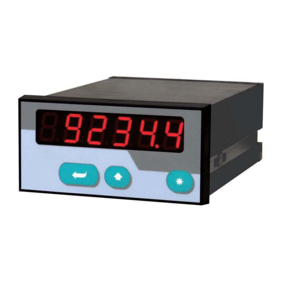
S S SI Indicators for Use with
Single-Turn or Multi-Turn SSI Encoders
SSI d isplay unit only
:
:
SSI d isplay unit with analogue output
:
SSI d isplay unit with two presets and outputs
:
SSI d isplay unit with serial interface RS232 and RS485
Clear LED display (15 mm / 0.59'' size) with adjustable brightness
Master- or Slave operation with clock rates up to 1 MHz
Suitable for all SSI formats from 8 to 32 bits
Numerous supplementary functions like Linearization, Bit Blanking etc.
Operating Instructions
Page 1 / 43
Advertisement
Table of Contents

Related Manuals for Hein Lanz D1-333-121-34 Series

Summary of Contents for Hein Lanz D1-333-121-34 Series
- Page 1 S S SI Indicators for Use with Single-Turn or Multi-Turn SSI Encoders SSI d isplay unit only SSI d isplay unit with analogue output SSI d isplay unit with two presets and outputs SSI d isplay unit with serial interface RS232 and RS485 Clear LED display (15 mm / 0.59’’...
- Page 2 S S afety Instructions This manual is an essential part of the unit and contains important hints about function, correct handling and commissioning. Non-observance can result in damage to the unit or the machine or even in injury to persons using the equipment! The unit must only be installed, connected and activated by a qualified electrician It is a must to observe all general and also all country-specific and application-...
-
Page 3: Table Of Contents
T T able of Contents Terminal Assignment ....................4 1.1. Power Supply ..........................5 1.2. Aux. Voltage Output ........................5 1.3. Control Inputs A, B and C ......................5 1.4. Adjustable Analogue Output ( only) ................6 1.5. Optocoupler (transistor) outputs ( only) ................6 1.6. -
Page 4: Terminal Assignment
1. Terminal Assignment : Display unit only All connections are as shown below, except for terminals 8, 9 and 10 which are unconnected : Display with analogue output : : Display with two presets and outputs : Display with serial interface Page 4 / 43... -
Page 5: Power Supply
1 1 .1. Power Supply The unit accepts DC supply from 17 V to 30 V when using terminals 1 and 2. The consumption depends on the level of the supply voltage (typical 130mA at 30V or 190mA at 17V, plus current taken from aux. output). For AC supply the terminals 0 VAC, 115 VAC or 230 VAC can be used. -
Page 6: Adjustable Analogue Output ( Only)
T T ypical input circuit of control input The minimum pulse duration on the Reset input (C) must be 5 msec. 1.4. Adjustable Analogue Output only) A voltage output is available, operating in a range of 0 ... +10 V or –10 V ... +10 V according to setting. -
Page 7: Serial Rs232 / Rs485 Interface ( Only)
1 1 .6. Serial RS232 / RS485 interface ( Ex factory the unit is set to RS232 communication. This setting can be changed to RS485 (2-wire) by means of an internal DIL switch. To access the DIL switch, you must remove the screw terminal connectors and the backplane. -
Page 8: How To Operate The Front Keys
2 2 . How to Operate the Front Keys For setup and other operations the unit uses three front keys which subsequently will be denominated as follows: ENTER (Input) (Setting) (Command) The functions of the keys are depending on the actual operating state of the unit. The following three operating states apply: Normal display state Setup state... -
Page 9: Selection And Setting Of Parameters
2 2 .2. Selection and Setting of Parameters 2.2.1. How to select a parameter The E E NTER key will scroll through the menu. The S S ET key allows to select the corresponding item and to change the setting or the numeric value. After this, the selection can be stored by ENTER again, which automatically changes over to the next menu item. -
Page 10: Teach Operation
2 2 .3. Teach operation The Time-out function will be switched off during all Teach operations Function ENTER will conclude or abort any Teach operation in progress SET function is fully similar to normal set-up operation Cmd will store the display value to the register and will change over to the next interpolation point. -
Page 11: The Operator Menu
3 3 . The Operator Menu The menu provides one section with “Basic Parameters” and another section with “Operational Parameters”. On the display you will only find those parameters which have been enabled by the basic settings. E.g. when the Linearisation Functions have been disabled in the basic set- up, the associated linearization parameters will also not appear in the parameter menu. -
Page 12: Overview Of Operational Parameters
3 3 .2. Overview of Operational Parameters Preselection 1 Preselection 2 M-Factor M-Factor M-Factor M-Factor D-Factor D-Factor D-Factor D-Factor P-Factor P-Factor P-Factor P-Factor Decimal point Decimal point Decimal point Decimal point Display Display Display Display Hi_Bit (MSB) Hi_Bit (MSB) Hi_Bit (MSB) Hi_Bit (MSB) Lo_Bit (LSB) Lo_Bit (LSB) -
Page 13: Setup Procedure
4 4 . Setup Procedure For better understanding the following sections 4.1 and 4.2 explain settings for the display only. Model-specific settings for Analogue Output, Preselections and Serial Link will be explained separately, later. 4.1. Basic Parameters The subsequent settings are of unique nature and must only be made upon the very first setup. The basic setup selects the desired operation mode of the unit, the input characteristics PNP/NPN and the desired brightness of the LED display. - Page 14 M M enu S S etting Range D D efault Code Locking Interlock of keypad access (see 2.5) no: Keypad accessible at any time All: Keypad interlock for all functions P-Free: Keypad interlock except for Preselection Settings Pres 1 und Pres 2 (model Linearization Mode For details please see 6.1 und 6.2.
-
Page 15: Operational Parameters
4 4 .2. Operational Parameters Menu Setting Range Default Factor *): -9.999 … 9.999 1.000 Multiplying factor for the SSI value (after consideration of possible bit blanking) Factor *): 0.001 … 9.999 1.000 Dividing factor for the SSI value (after consideration of possible bit blanking) Factor *): -199999 …... - Page 16 M M enu S S etting Range D D efault Direction riGht riGht LEFt Parameter to negate the SSI value, resulting in reversal of the direction of the encoder count. riGht: ascending values with forward motion LEFt:: decreasing values with forward motion Error: 0 ...
- Page 17 M M enu S S etting Range D D efault Reset A Reset command is available to store the actual SSI position to register „Zero Position“. As a result, the display value will become zero at the actual encoder position, and all further operation will refer to this new datum point.
-
Page 18: Additional Parameters For The Analogue Output (Model )
4 4 .3. Additional Parameters for the Analogue Output (model The following additional settings for the analogue output appear in the Basic Menu: Menu Setting Range Default Analogue Characteristics You can set the following output options: +/- 10 V (bipolar), 0 - 10 V (positive only), 4 - 20 mA 0 - 20 mA. - Page 19 The subsequent example shows how to convert the display range from 1400 to 2000 into an analogue signal of 2 - 10 volts. A- - ChAr = 0 - - 1 1 0 V AnAbEG = 1400 OFFSEt = = 2.000 AnAEnd = = 2000 GAin...
-
Page 20: Additional Parameters For Preselections And Switching Outputs (Model )
4 4 .4. Additional Parameters for Preselections and Switching Outputs (model The following additional settings for the Preselections appear in the Basic Menu: Menu Default Switching Characteristics of Output 1 Greater/Equal. Output to switch statically ON when Display Value Preselection1 Lower/Equal. - Page 21 The following Operational Parameters provide setting of the switching thresholds: M M enu S S etting Range D D efault Preselection 1: -199999.. 10000 999999 eselection 2: -199999.. 5000 999999 The direction of the Hysteresis effect depends on the setting of the switching characteristics. With the settings „GE“...
-
Page 22: Additional Parameters For Units With Serial Interface (Model )
4 4 .5. Additional Parameters for Units with Serial Interface (model The following additional settings for serial communications appear in the Basic Menu: Menu Setting Range Default Unit Number 0..99 1 1 1 You can assign any unit number between 11 and 99. - Page 23 The following Operational Parameters provide configuration of the serial interface: M M enu S S etting Range D D efault Serial Timer: 0,000 0,100 sec Setting 0,000 allows manual activation of a serial data 0,010 sec transmission at any time. All other settings specify the cycle …...
- Page 24 4 4 .5.1. PC-Mode Communication with PC - Mode allows free readout of all parameters and registers of the unit. The subsequent example shows the details of communication for serial readout of the actual display value. The general string to initiate a request has the following format: EOT = Control Character (Hex 04) AD1 = Unit Address, High Byte...
- Page 25 4 4 .5.2. Printer Mode The Printer Mode allows cyclic or manual activation of transmissions of the specified register data. The corresponding register can be specified by means of parameter „S-Code“. Another parameter named „S-mod“ allows selection between two different string types: „S- mod“...
-
Page 26: Hints For Application
5 5 . Hints for Application 5.1. Master and Slave Operation Set register “Mode” to position “Master” when the unit should generate the clock signal for the encoder. In this case the clock terminals (CLK) are configured as clock outputs. When your encoder receives already its clock from another device and the unit should only “listen”... -
Page 27: Evaluation Of Encoder Bits
With Master operation, therefore other settings will result in generation of the next upper or lower value according to above list. With all settings <250.0 kHz the error between set rate and generated rate becomes negligible. It is mandatory to set the Baud rate also with Slave operation. In this case, however, the setting serves only to determine the pause time for correct synchronization (pause is detected after 4 clock cycles). -
Page 28: Scaling Of The Display
5 5 .3. Scaling of the Display Under consideration of the scaling parameters which have been described previously, the final display value of the unit results from Encoder SSI data are always positive only. Where also negative values should be indicated, this can be achieved by corresponding setting of the parameters „0-Position“... -
Page 29: Basic Modes Of Operation
5 5 .4. Basic Modes of Operation 5.4.1. Normal SSI display Normal operation provides calculation of the display value from the SSI encoder data and the settings of the scaling factors. Negative values can be achieved by corresponding setting of the zero-position, or by inversion of the direction bit. - Page 30 Course of display with positive counting direction Course of display with negative counting direction Page 30 / 43...
- Page 31 5 5 .4.2. Round-Loop Function This mode of operation is used frequently with rotating round tables or similar applications, where the absolute encoder information is only used for a limited and repeating range of the encoder (like one revolution of the table, which must not at the same time mean one revolution of the encoder shaft).
- Page 32 5 5 .4.3. Operation with Zero-Crossing As a special advantage, the round-loop mode can be used to bypass the mechanical encoder overflow position, because in this mode the unit continues with steady operation, even while the SSI encoder signal passes the mechanical overflow position from maximum to zero. This feature can help to avoid mechanical adjusting of the encoder zero position with many applications, when no other means for the mechanical zero definition is available.
-
Page 33: Testing Functions
5 5 .5. Testing Functions The test menu can be accessed while doing the basic set up, as shown in section 4.1. Most of these tests are for factory use only, but the following tests may also be helpful for the user: Menu Selection Text... -
Page 34: Special Functions
6 6 . Special Functions 6.1. Linearization This function allows converting a non-linear input signal into a linear presentation or vice- versa. There are 16 interpolation points available, which can be freely arranged over the whole measuring range in any distance. Between two points the unit automatically will interpolate straight lines. - Page 35 Application Example: The picture below shows a Watergate where the opening is picked up by means of an SSI encoder. We would like to display the clearance of the gate "d", but the existing encoder information is proportional to the opening angle . Page 35 / 43...
-
Page 36: Manual Input Or „Teaching" Of The Interpolation Points
6 6 .2. Manual Input or „Teaching“ of the Interpolation Points Interpolation points to form the linearization curve can be entered one after another, using the same procedure as for all other numeric parameters. This means you will enter all parameters P01_x to P16_x and P01_y to P16_y manually by keypad. - Page 37 Once we have reached and stored the last interpolation points P16_x/y, the routine will restart with P01_x again. You are free to double-check your settings once more or to make corrections. To conclude the Teach procedure, keep ENTER down for about 2 seconds. In the display you will read “StOP”...
-
Page 38: Technical Appendix
7 7 . Technical Appendix 7.1. Dimensions 110,0 (4.331’’) 96,0 (3.780’’) Panel cut out: 91 x 44 mm (3.583 x 1.732’’) Page 38 / 43... -
Page 39: Technical Specifications
7 7 .2. Technical Specifications Supply voltage AC : 115/230 V (+/- 12.5 %) Supply voltage DC : 24 V (17 – 30 V) Consumption (without sensor) : 17 V: 190 mA, 24 V: 150 mA, 30 V: 120 mA AC Power : 7.5 VA Aux. -
Page 40: Parameter-List
7 7 .3. Parameter-List in - - ax - - efault - - Denomination Text Positions Characters Value Value Value Code NPN / PNP CHAr Brightness briGht Code Locking Code SSI-Mode modE SSI-Bits bitS SSI-Format Form SSI-Baudrate bAUd 1000.9 100.0 SSI-Test tESt M-Factor... - Page 41 Min - Max - Default - Ser. D D enomination Text Positions Characters Value Value Value Code Ser. Format S-Form Baud Rate S-bAUd Ser. Address S-Unit Ser. Timer S-tim 9999 Ser. Mode S-mod Register-Code S-CodE Linear. Mode LinEAr Linear. Point 1 P01_H -199999 999999...
-
Page 42: Commissioning Form
7 7 .4. Commissioning Form Date Software: Operator: Serial Number: General Setting: SSI-Mode: SSI-Bits: SSI-Format: SSI-Baud Rate (kHz): SSI-Test: Characteristics: Brightness Code Locking: Linearization Mode: Model Output Char.: Analogue Offset: Analogue Gain: Model Presel. Mode 1 Presel. Mode 2: Hysteresis 1 Hysteresis 2: Model Serial Unit Nr:... - Page 43 L L inearization P1(x): P1(y): P9(x): P9(y): P2(x): P2(y): P10(x): P10(y): P3(x): P3(y): P11(x): P11(y): P4(x): P4(y): P12(x): P12(y): P5(x): P5(y): P13(x): P13(y): P6(x): P6(y): P14(x): P14(y): P7(x): P7(y): P15(x): P15(y): P8(x): P8(y): P16(x): P16(y): Page 43 / 43...
Need help?
Do you have a question about the D1-333-121-34 Series and is the answer not in the manual?
Questions and answers