Sony CDP-CA70ES Service Manual
Hide thumbs
Also See for CDP-CA70ES:
- Operating instructions manual (43 pages) ,
- Product information (2 pages) ,
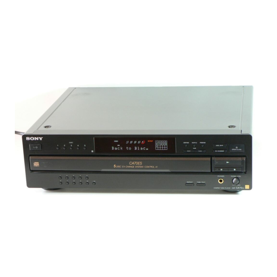
- Product view (1 page)
Table of Contents
Advertisement
Quick Links
SERVICE MANUAL
Manufactured under license from Dolby Laboratories
Licensing Corporation.
"DOLBY" and the double-D symbol a are trademarks
of Dolby Laboratories Licensing Corporation.
Compact Disc Player
Laser
Semiconductor laser (λ = 780 nm)
Emission duration: continuous
Laser output
Max 44.6 µW*
* This output is the value measured at a
distance of 200 mm from the objective
lens surface on the Optical Pick-up
block with 7 mm aperture.
Frequency response
2 Hz to 20 kHz ± 0.3 dB
Signal-to-noise ratio
More than 117 dB
Dynamic range
More than 99 dB
Harmonic distortion
Less than 0.0025%
Channel separation
More than 110 dB
Output
Jack
type
LINE OUT
Phono
jacks
DIGITAL OUT
Optical
(OPTICAL)
output
connector
PHONES
Stereo
phone jack
MICROFILM
CDP-CA70ES
SPECIFICATIONS
Maximum
Load
output
impedance
level
2V
Over 10 kΩ
(at 50 kΩ)
–18 dBm
Wave length:
660 nm
32 Ω
15 mW
Model Name Using Similar Mechanism
CD Mechanism Type
Base Unit Name
Optical Pick-up Name
General
Power requirements
120 V AC, 60 Hz
Power consumption
15W
430 × 125 × 400 mm
Dimensions (approx.)
(17 × 5 × 15
(w/h/d)
Mass (approx.)
6.4 kg (14 lbs 2 oz)
Supplied accessories
Audio cord (2 phono plugs–2 phono plugs) (1)
Remote commander (remote) (1)
R6(SIZE AA)batteries (2)
Design and specifications are subject to change without notice.
COMPACT DISC PLAYER
US Model
Canadian Model
NEW
CDM27I
BU-5BD25
KSS-213B/S-N
3
/
in.) incl. projecting parts
4
Advertisement
Table of Contents

Subscribe to Our Youtube Channel
Related Manuals for Sony CDP-CA70ES


Summary of Contents for Sony CDP-CA70ES
- Page 1 CDP-CA70ES SERVICE MANUAL US Model Canadian Model Manufactured under license from Dolby Laboratories Model Name Using Similar Mechanism Licensing Corporation. CD Mechanism Type CDM27I “DOLBY” and the double-D symbol a are trademarks Base Unit Name BU-5BD25 of Dolby Laboratories Licensing Corporation.
-
Page 2: Table Of Contents
TABLE OF CONTENTS SERVICE NOTE ··························································· 4 GENERAL ······································································ 7 DISASSEMBLY 3-1. Front Panel ········································································· 9 3-2. Disc Table Assembly and Disc Table and Press Pulley ······ 9 3-3. Main Board ······································································· 10 3-4. CDM Assembly ································································ 10 3-5. Optical Pick-up Block Assembly ····································· 11 3-6. - Page 3 CRITIQUES POUR LA SÉCURITÉ DE FONCTIONNEMENT. NE COMPONENTS WITH SONY PARTS WHOSE PART NUMBERS REMPLACER CES COMPOSANTS QUE PAR DES PIÈSES SONY APPEAR AS SHOWN IN THIS MANUAL OR IN SUPPLEMENTS DONT LES NUMÉROS SONT DONNÉS DANS CE MANUEL OU PUBLISHED BY SONY.
- Page 4 SECTION 1 SERVICING NOTE HOW TO OPEN THE DISC TRAY WHEN POWER SWITCH TURNS OFF Insert a tapering driver into the aperture of the unit bottom, and turn in the direction of arrow (to OUT direction). * To close the disc tray, turn driver in the reverse direction (to IN direction).
- Page 5 SHIPMENT MODE Performed when returning the unit to the customer. Custom File Erases all custom files and initializes settings. Procedure: Remove the discs from all trays. While pressing the DISC 2 button and 3 button. press the 1/u button to turn ON the power. “NO DISC”...
- Page 6 Table 2: CD-TEXT TEST DISC Recorded Contents and Display (In this unit, some special characters cannot be displayed. This is not a fault.) TRACK Recorded contents Display 0 dB L & R are not displayed ! ” # $ % & ’ (21h to 27h)1kHz 0dB L&R N All the same + , –...
-
Page 7: General
SECTION 2 GENERAL Identifying the Parts Front Panel 3 4 56 7 !º !¶ !§ !∞ !¢ !£ !™ !¡ POWER (1/u) switch ” (CD PLAY) button !º DISC (1–5) buttons p (CD STOP) button !¡ CONTINUE button PHONE LEVEL button !™... -
Page 9: Disassembly
SECTION 3 DISASSEMBLY Note : Follow the disassembly procedure in the numerical order given. 3-1. FRONT PANEL 1 Remove top cover. 2 Eject the disc table referring to SERVICING NOTE (Page 4). !£ Three screws 9 Connector M 3 × 12 (CN403) !™... -
Page 10: Main Board
3-3. MAIN BOARD 6 Seven screws 8 Main board (BVTP 3 × 8) 2 Connector (to Rotary encoder) 4 Two screws (BVTT 3 × 6) 3 Flat type wire (23 core)(CN401) 8 Flat type wire (6 core)(CN504) 7 Two claws 1 Connector (CN601) 5 Two screws (BV/ring) -
Page 11: Optical Pick-Up Block Assembly
3-5. OPTICAL PICK-UP BLOCK ASSEMBLY 2 Screw (M 3 × 12) 3 Two screws (PTPWH 2.6 × 6) 4 Two screws (PTPWH 2.6 × 6) 8 Optical pick-up block assembly 6 Compression spring (BU) 1 Flat type wire (23 core) (BD board, to CN101) 5 Holder (BU) 7 Compression spring (BU) - Page 12 SECTION 4 TEST MODE ADJ MODE Buttons and Corresponding Button Numbers Button Button Number or Display 1. Chuck the CD first, and then turn OFF the power. CONTINUE 2. Short-circuit the test point (TP2:ADJ) of the main board and ground with a lead wire. SHUFFLE 3.
- Page 13 All lit 9 10 11 12 13 14 15 16 17 18 19 20 Partial lighting 1 Light alternately Partial lighting 2 Light alternately ˜ Light alternately — 13 —...
- Page 14 AGING MODE This unit is equipped with an aging mode to check operations of the mechanism deck. • When faults occur: Aging stops, and the state when aging stopped is displayed on the fluorescent display tube. • When no fault has occurred: Aging is continued repeatedly.
-
Page 15: Electrical Block Checking
SECTION 5 ELECTRICAL BLOCK CHECKING Note: Note: 1. CD Block is basically designed to operate without adjustment. A clear RF signal waveform means that the shape “◊” can be clearly Therefore, check each item in order given. distinguished at the center of the waveform. 2. - Page 16 Check the level B of the oscilliscope's waveform and the A (DC voltage) of the center of the Traverse waveform. Confirm the following : A/B x 100 = less than ± 22% Traverse waveform Center of the waveform A (DC voltage) + 0.7 level : 1.3 mVp-p...
-
Page 17: Diagrams
SECTION 6 DIAGRAMS 6-1. CIRCUIT BOARDS LOCATION BD board TABLE MOTOR board SENSOR board DISPLAY board MAIN board FUNCTION board 10 KEY board LOADING MOTOR board HP board — 17 —... - Page 18 • Waveforms THIS NOTE IS COMMON FOR PRINTED WIRING BOARDS AND SCHEMATIC DIAGRAMS. IC101&¡ (XTAI) IC501#™ (XTAL) (In addition to this, the necessary note is printed in each block.) 2.7Vp-p 4.8Vp-p For schematic diagrams. Note: 16.9MHz 10 MHz • All capacitors are in µF unless otherwise noted. pF: µµF 50 WV or less are not indicated except for electrolytics and tantalums.
-
Page 19: Block Diagram
CDP-CA70ES 6-2. BLOCK DIAGRAM DIGITAL SERVO/ IC405 OPTICAL PICK-UP IC101 BLOCK (KSS-213 B) RF AC D OUT D IN DIGITAL • SIGNAL PATH DSP/ CURRENT PULSE PHOTO DETECTOR RF AMP D/A CONV. D/A CONV. : CD IC103 IC301 IC302 L.P.F... -
Page 20: Schematic Diagram Bd Section
CDP-CA70ES 6-3. SCHEMATIC DIAGRAM BD SECTION • See page 18 for Waveforms. • See page 38 for IC Block Diagrams. • See page 40 for IC Pin Functions. (IC101) B/S-N (FE2) (FE1) MAIN BOARD CN401 (Page 27) The components identified by Les composants identifiés par... -
Page 21: Printed Wiring Board Bd Section
CDP-CA70ES 6-4. PRINTED WIRING BOARD BD SECTION • See page 17 for Circuit Boards Location. (FE1) (FE2) MAIN BOARD CN401 (Page 25) KSS-213B/S-N • Semiconductor • Semiconductor Location Location Ref. No. Location Ref. No. Location IC102 IC101 IC103 Q101 — 23 —... -
Page 22: Printed Wiring Board Main Section
CDP-CA70ES 6-5. PRINTED WIRING BOARD MAIN SECTION • See page 17 for Circuit Boards Location. SENSOR BOARD • Semiconductor (Page 32) Location MAIN BOARD BD BOARD Ref. No. Location (Page 24) D301 D381 IC405 D531 E-11 DIGITAL D601 D602 D603... -
Page 23: Schematic Diagram Main Section (1/2)
CDP-CA70ES 6-6. SCHEMATIC DIAGRAM MAIN SECTION (1/2) • See page 38 for IC Block Diagrams. • See page 42 for IC Pin Function. DISPLAY (Page 21) (Page 34) (Page 34) (Page 31) (Page 29) (Page 31) TP1 (AFADJ) JW137 TP2 (ADJ) -
Page 24: Schematic Diagram Main Section (2/2)
CDP-CA70ES 6-7. SCHEMATIC DIAGRAM MAIN SECTION (2/2) • See page 37 for IC Block Diagrams. • See page 25 for Printed Wiring Board. (Page 28) L515 (Page 31) C383 0.1uF — 29 — — 30 —... -
Page 25: Schematic Diagram Hp Section
CDP-CA70ES 6-8. SCHEMATIC DIAGRAM HP SECTION 6-9. PRINTED WIRING BOARD HP SECTION • See page 17 for Circuit Boards Location. HP BOARD TABLE MOTOR BOARD (Page 30) W701 M802 1-650-082- LOADING MOTOR (11) (Page 26) SENSOR BOARD CN801 D802 D801... -
Page 26: Schematic Diagram Display Section
CDP-CA70ES 6-10. SCHEMATIC DIAGRAM DISPLAY SECTION • See page 42 for IC Pin Functions. — 33 — — 34 —... -
Page 27: Printed Wiring Board Display Section
CDP-CA70ES 6-11. PRINTED WIRING BOARD DISPLAY SECTION • See page 17 for Circuit Boards Location. (Page 26) (Page 26) • Semiconductor Location Ref. No. Location D801 D802 IC801 B-13 IC802 Q801 Q802 Q803 Q804 B-10 — 35 — — 36 —... -
Page 28: Ic Block Diagrams
6-12. IC BLOCK DIAGRAMS IC301 CXD8505BQ (MAIN BOARD (2/2)) IC103 CXA2568M (BD BOARD) IC551 BA6780 (MAIN BOARD (1/2)) APC PD AMP LC/PD VIN1 VIN2 LD_ON HOLD 32 31 30 29 28 27 26 25 24 23 22 21 20 AGCVTH VREF FIN1 FIN2... - Page 29 IC802 LC75721E (DISPLAY BOARD) CG ROM SHIFT DC RAM REGISTER CG RAM ADDRESS ADDRESS AD RAM RESISTOR COUNTER BLINKCYCLE BLINK RESISTOR GENERATOR DISPLAY DISPLAY RESISTOR CONTROL DUTYCYCLE DUTY RESISTOR GENERATOR N.C. GLID GLID N.C. RESITOR CONTROL TEST INSTRUCTION CONTROL RESISTOR OSC2 TIMING DRIVER...
-
Page 30: Ic Pin Functions
6-13. IC PIN FUNCTIONS • IC101 DIGITAL SIGNAL PROCESSOR (CXD2585Q) (BD BOARD) Pin No. Pin Name Function DVDD — Digital power supply XRST System reset “L” : reset MUTE Muting input “H” : mute DATA Serial data input, supplied from CPU XLAT Latch input, supplied from CPU CLOK... - Page 31 Pin No. Pin Name Function Tracking error signal input Center servo analog input RFDC RF signal input ADIO Test pin (Not used) AVSS0 — Analog ground IGEN Stabilized current input for operational amplifiers AVDD0 — Analog power supply ASYO EFM full swing output ASYI Asymmetry comparate voltage input RFAC...
- Page 32 • IC501 SYSTEM CONTROL (CXP84648-052Q) (MAIN BOARD) Pin No. Pin Name Function SRAM address 5 SRAM address 4 SRAM address 3 SRAM address 2 — Not used SRAM data 0 SRAM data 1 SRAM data 2 SRAM data 3 SRAM data 4 SRAM data 5 SRAM data 6 SRAM data 7...
- Page 33 Pin No. Pin Name Function KEY3 Key input 3 CD123 Command mode switch KEY1 Key input 1 KEY0 Key input 0 ADJ input from keys and CDs T_SENS Table sensor Display latch Command clock LDON Laser diode ON DATA Command data SQCLK Sub-Q clock SUBQ...
-
Page 34: Exploded Views
4-922-921-71 BUTTON (POWER) 1-672-377-11 HP BOARD 4-951-620-01 SCREW (2.6 × 8), +BVTP 1-672-376-11 FUNCTION BOARD 4-996-841-01 HOLDER (FL) 4-942-568-41 EMBLEM (NO.5), SONY 1-672-375-11 10 KEY BOARD 1-769-456-11 WIRE (FLAT TYPE) (15 CORE) 4-972-223-21 CASE A-4724-543-A DISPLAY BOARD, COMPLETE 3-710-901-11 SCREW, TAPPING... -
Page 35: Back Panel And Disc Table Section
7-2. BACK PANEL AND DISC TABLE SECTION supplied M801 not supplied not supplied not supplied not supplied not supplied Ref. No. Part No. Description Remarks Ref. No. Part No. Description Remarks * 51 4-957-299-41 TABLE (B), DISC * 67 4-957-298-41 TABLE (A), DISC 4-957-304-01 BELT (RM) * 70 3-703-244-00 BUSHING (2104), CORD... -
Page 36: Chassis Section
7-3. CHASSIS SECTION BU-5BD25 supplied T601 M802 supplied Ref. No. Part No. Description Remarks Ref. No. Part No. Description Remarks 4-957-283-11 WASHER (5), STOPPER 4-934-375-01 GEAR (LOADING B) 4-957-288-01 GEAR (MAIN) 4-957-285-11 LEVER, SET 4-957-287-01 GEAR (REV) 4-962-087-01 SPRING (S), TENSION 4-957-286-11 GEAR (U/D) 1-647-363-11 LOADING MOTOR BOARD 1-466-996-11 ENCODER, ROTARY... -
Page 37: Base Unit Section (Bu-5Bd22)
7-4. BASE UNIT SECTION (BU-5BD25) M101 M102 Ref. No. Part No. Description Remarks Ref. No. Part No. Description Remarks ! 151 8-848-379-31 DEVICE, OPTICAL KSS-213B/S-N 4-917-564-01 GEAR (P), FLATNESS 1-769-069-11 WIRE (FLAT TYPE) (16 CORE) * 157 A-4724-002-A BD (A) BOARD, COMPLETE 2 ×... -
Page 38: Electrical Parts List
SECTION 8 10 KEY ELECTRICAL PARTS LIST NOTE: • Due to standardization, replacements in the • RESISTORS When indicating parts by reference number, parts list may be different from the parts All resistors are in ohms. please include the board name. specified in the diagrams or the components METAL: metal-film resistor The components identified by mark ! or... - Page 39 DISPLAY Ref. No. Part No. Description Remarks Ref. No. Part No. Description Remarks R106 1-216-061-00 METAL CHIP 3.3K 1/10W < INDICATOR TUBE > R107 1-216-061-00 METAL CHIP 3.3K 1/10W R108 1-216-073-00 METAL CHIP 1/10W FL801 1-517-664-11 INDICATOR TUBE, FLUORESCENT R109 1-216-121-91 RES,CHIP 1/10W R110...
- Page 40 FUNCTION LOADING MOTOR MAIN Ref. No. Part No. Description Remarks Ref. No. Part No. Description Remarks 1-672-376-11 FUNCTION BOARD A-4724-655-A MAIN BOARD, COMPLETE ************** ******************** 7-685-871-01 SCREW +BVTT 3 × 6 (S) < CONNECTOR > CN802 1-750-186-11 CONNECTOR, BOARD TO BOARD 6P <...
- Page 41 MAIN Ref. No. Part No. Description Remarks Ref. No. Part No. Description Remarks C361 1-124-584-00 ELECT 100uF < TERMINAL > C382 1-102-852-91 CERAMIC 47PF C383 1-164-159-11 CERAMIC 0.1uF EB001 1-537-770-21 TERMINAL BOARD, GROUND C401 1-126-933-11 ELECT 100uF C402 1-126-934-11 ELECT 220uF <...
- Page 42 MAIN Ref. No. Part No. Description Remarks Ref. No. Part No. Description Remarks R111 1-215-407-00 METAL 1/4W R338 1-249-429-11 CARBON 1/4W R112 1-215-407-00 METAL 1/4W R351 1-247-807-31 CARBON 1/4W R113 1-215-451-00 METAL 1/4W R352 1-247-807-31 CARBON 1/4W R114 1-215-451-00 METAL 1/4W R381 1-249-425-11 CARBON...
- Page 43 SENSOR TABLE MOTOR Ref. No. Part No. Description Remarks Ref. No. Part No. Description Remarks 1-647-362-11 SENSOR BOARD ACCESSORIES & PACKING MATERIALS ************ ******************************* < CONNECTOR > 1-475-680-11 REMOTE COMMANDER (RM-DC80) 1-590-925-31 CORD, CONNECTION (AUDIO) CN801 1-573-383-11 PIN, CONNECTOR (PC BOARD) 2P 1-777-172-11 CORD, CONNECTION (CONTROL A1)(CND) CN802 1-750-243-11 SOCKET, CONNECTOR 6P...
- Page 44 CDP-CA70ES Sony Corporation 99E167023-1 Home Audio Company 9-928-898-11 Printed in Singapore ©1999.5 — 54 — Published by Quality Assurance Dept.
Need help?
Do you have a question about the CDP-CA70ES and is the answer not in the manual?
Questions and answers