Advertisement
Quick Links
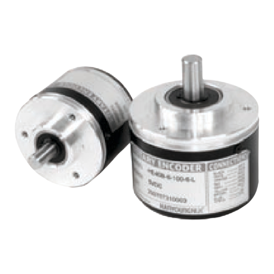
Rotary Encoder
HE series
INSTRUCTION MANUAL
Thank you for purchasing HANYOUNG product.
Please check whether the product is the exactly same as
you ordered. Before using the product, please read this
instruction manual carefully.
Safety information
CAUTION
1. Before using the product you purchased, make sure that it is exactly what you ordered.
2. Make sure that there is no damage or abnormality of the product during the delivery.
3. The transmitter for measuring the length is composed of precision parts, so can easily be
damaged with external impact, therefore handle with care.
4. The shield wire of the transmitter for length measurement is not connected to the case.
5. When the product gets wet, the inspection is essential because there is danger of an electric
leakage or fire.
6. For the continuous and safe use of this product, the periodical maintenance is recommended.
7. If you use the product with methods other than specified by the manufacturer, there may
be bodily injuries or property damages.
On Mega Test
An internal pressure of 500V DC exists between the Case and the electric circuit, however, there
are dangers of damage the electrical circuit if voltage is applied accidentally, so do not perform
mega tests.
On Installation
1. During installation, do not apply impact on or twist the shaft of the transmitter for length
measurement.
2. During installation, do not apply excessive force when combining the shaft of transmitter for
length measurement and the instrument.
3. During installation, take caution because the life span of the transmitter for length
measurement is dependent on the usage condition and the environment.
4. Do not decompose, modify, revise or repair this product. This may be a cause of malfunction,
electric shock or fire.
5. Reassemble this product while the power is OFF. Otherwise, it may be a cause of malfunction
or electric shock.
About Wiring
1. Separate an input signal cable from an output signal cable. If separating is not possible,
please use the input signal cable after shielding it.
2. If there is excessive noise from the power supply, using insulating transformer and noise filter
is recommended.
3. Do not connect anything to the unused terminals.
4. After checking the polarity of terminal, connect wires at the correct position.
5. As for wiring, ensure they are as short as possible.
6. Having the same pipe for wiring of the transmitter for length measurement with the power line
or an identical connection could cause malfunction, therefore please take caution.
7. Wrong connection of the wiring of transmitter for length measurement may damage the
internal circuit. Please take sufficient caution.
About vibration
1. If intense vibration or impact is applied on the transmitter for length measurement, the wrong
pulse is generated causing malfunction, therefore, absolute care is necessary when selecting
the installation and disposition location.
2. As much as the amount of pulse per cycle, the slit gap of rotation slit is narrower, therefore can
be easily affected by vibration, and the vibration applied during slow rotation or when
stationary, may get transmitted to the shaft or the main body, causing wrong pulse generation,
therefore, please take caution. The vibration applied to the transmitter for length measurement
can become a cause for wrong pulse generation, so please take caution in terms of
installation location or location for attachment.
For noise prevention
The caution on the safety stated above, must be kept, otherwise malfunction
can be induced.
MAIN PRODUCTS
- DIGITAL : Temperature Controller, Counter, Timer,Speedmeter,
- SENSOR : Proximity Sensor/Photo Electric Sensor,
- ANALOG : Timer, Temperature Controller
HEAD OFFICE
1381-3, Juan-Dong, Nam-Gu Incheon, Korea
TEL: (82-32)876-4697 FAX : (82-32)876-4696
Distance from
Wiring of Rotary Encoder
control box
As for
Rotary Encoder
Case,
connect on the control board case
by 3~5.5MM electric wire. For the
30 m Max.
0 V terminal, connect on the
control board case with identical
type of electrical wire and earth it.
Perform as indicated above,
30 m Min.
and earth the Rotary Encoder.
Tachometer, Panel Meter, Recorder
Rotary Encoder, Optical Fiber Sensor,
Pressure Sensor
Ratings
HE40B
6
Shaft external
Pulse number per
Mode
diameter
*1,10,50,60,100,
6 : 6 mm
120,200,250,300,360
HE40B
8 : 8 mm
,400,500,512,600,80
40 mm
Shaft type
(Option)
0,1000,1024,2000,20
48,3000,3600,5000
*1,10,50,60,100,
HE50B
120,200,250,300,360
8 : 8 mm
50 mm
,400,500,512,600,80
Shaft type
0,1000,1024,2000,20
48,3000,3600,5000
" * " mark : Only A, B phase can output (Line Drive output is A, /A, B, /B)
The item that is not in the above revolution is order made product
Specification
HE
Mode #
- - - -N-
Output type
NPN Voltage output
A, B, Z phase
Output type
Phase difference between A. B phase:
Phase difference
on Output
T/4
T/8(Cycle of A phase = T)
Max Response
300 kHz
Frequency
Power voltage
5 - 12 V d.c / 12 - 24 V d.c
Current
70 mA Max. (No-load) Line Drive output below 30 mA (No-load)
Consumption
Connection method
WIRE
Load voltage : 30 V Max.
Load Current : 30 mA Max.
Control output
Residual Voltage : 0.4 V Max.
1 Max.
Response Time
(Cable length 1.5 m / sink=30 mA)
40 : 40 gf
Starting Torque
50 : 80 gf
40 : 40 g
Moment of inertia
40 : Radial : Within 2 kgf, Thrust : Within 1 kgf
Permissible Shaft
50 : Radial : Within 2.5 kgf, Thrust : Within 1.2 kgf
Loading
Max. Permissible
5000 rpm
Revolution
1.2 x 10
8
Bearing Life
Over 100
Insulation Resistance
800 V a.c (Between terminal and case at 60Hz for 1 minute)
Dielectric strength
10~55Hz (Cycle for 1 minute), Double amplitude width: 1.5mm, Each X Y Z direction for 2 hours
Vibration Resistance
40 : 50 G Max., 50 : 75 G Max.
Shock Resistance
Operating Ambient
-10 ~ 60 (Without condensation), Storage Temperatur : -25 ~ 85
Temperature
Operating Ambient
35 ~ 85 % R.H.
Humidity
Protection IP 50 (IEC Standard)
Protection
5 P,
5.0 mm, Length : 1.5 m, Shield cable
Wire Specification
(Line Driver Type : 8P, 5.0 mm, Length : 1.5 m, Shield cable)
Weight
40 : 170 g,
8.0 mm Coupling, Bracket ( 40mm Bracket Separate sales)
Accessory
600
3
T
Phase
Output type
revolution
type
2 : A,B
O : NPN
3 : A, B, Z
Open
3C : A, B,
collector
/Z
N : NPN
4 : A, /A,
Voltage
B, /B
T : Totem-
6 : A, /A,
pole
B, /B
L : Line driver
Z, /Z
(Line Drive:
(Standard :
5V d.c)
A, B, Z)
B
HE
B
HE
- - - -O-
- - - -T-
NPN Open collector output
Totem Pole Output
5 %
For Low
Load Current: 30 mA
Max.
Residual Voltage: 0.4 V
Max.
For High
Load Current: 10 mA
Max.
Residual Voltage: Above
-2.5V of rated voltage
Max.
1
(Cable length 1.5 m /
sink=10 mA)
(0.004 N m Max.)
(0.008 N m Max.)
Max., 50 : 80 g
Max.
/rpm : hour
(Base on 500 V d.c mega between terminal and case)
50 : 200 g
MI0115E080226
24
Power
Wire
voltage
Specification
5 : 5 V d.c
No mark:
12 : 12 V d.c
Standard type
(5-12 V d.c)
C : Connector
24 : 24 V d.c
(12-24 V d.c)
B
HE
B
- - - -L-
Line Driver Output
A,B,Z,A,B,Z phase
5 V d.c
5 %
For Low Load Current:
20 Max.
Residual Voltage: 0.4 V
Max.
For High
Load Current: 20 mA
Max.
Residual Voltage: 2.5 V
Max.
Max.
1
(Cable length 1.5 m /
sink = 30 mA)
Advertisement

Related Manuals for HANYOUNG NUX HE Series


Summary of Contents for HANYOUNG NUX HE Series
- Page 1 MI0115E080226 MAIN PRODUCTS Rotary Encoder - DIGITAL : Temperature Controller, Counter, Timer,Speedmeter, HE series Tachometer, Panel Meter, Recorder - SENSOR : Proximity Sensor/Photo Electric Sensor, Rotary Encoder, Optical Fiber Sensor, Pressure Sensor INSTRUCTION MANUAL - ANALOG : Timer, Temperature Controller Thank you for purchasing HANYOUNG product.
- Page 2 Aspect Dimension Output Circuit [Unit : mm] NPN Voltage Output NPN Open Collector Output 50 Axis Internal Circuit Internal Circuit Example of Example of of Encoder of Encoder external connection external connection outflow current Load 30mA Max. Output Output Inflow current 30mA Max.