Table of Contents
Advertisement
Advertisement
Table of Contents

Related Manuals for Kubota VS220-330


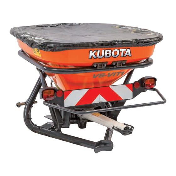
Summary of Contents for Kubota VS220-330
- Page 1 Technical service manual Basic book VS Pendulum spreaders Kubota...
- Page 2 VS600-800-1000 VS220-330 VS400-500 Date December 2016 Subject Basic machine book VS Pendulum Spreaders Kubota Place Kverneland Group Nieuw Vennep Hoofdweg 1278 2153 LR Nieuw Vennep The Netherlands Details Technical Service Manual...
-
Page 3: Table Of Contents
Table of contents 1. Model overview 2. Assambling instruction 2.1 Parts needed for standard VS220 without accessories 2.2 Parts needed for standard VS400 without accessories 2.3 Parts needed for standard VS400Viti without accessories 2.4 Parts needed for standard VS600 without accessories 2.5 Assembling VS 220-330 2.6 Assembling VS 400-500 2.7 Assembling VS 400-500Viti... -
Page 4: Model Overview
1 Model overview VS 220 VS 330 Basic Model VS 220 Basic Model VS 330 Hopper Capacity 7,8 ft³ (220 L) Hopper Capacity 7,8 ft³ (330 L) Hopper Width 3,6” (106 cm) Hopper Width 3,6” (106 cm) Weight 183 lbs (83kg) Weight 187 lbs (85kg) Cat. - Page 5 1 Model overview VS 400 VS 500 Basic Model VS 400 Basic Model VS 500 Hopper Capacity 14,1 ft³ (400 L) Hopper Capacity 17,7 ft³ (500 L) Hopper Width 4,9” (145 cm) Hopper Width 4,9” (145 cm) Weight 267 lbs (121kg) Weight 278 lbs (126kg) Cat.
- Page 6 1 Model overview VS 400 VITI VS 500 VITI Basic Model VS 500 VITI Basic Model VS 400 VITI Hopper Capacity 17,7 ft³ (500 L) Hopper Capacity 14,1 ft³ (400 L) Hopper Width 3,7” (115 cm) Hopper Width 3,7” (115 cm) Weight 278 lbs (126kg) Weight...
- Page 7 1 Model overview VS 600 VS 800 VS 1000 Basic Model Basic Model VS 600 VS 800 Basic Model VS 1000 Hopper Capacity Hopper Capacity 21,2 ft³ (600 L) 28,3 ft³ (800 L) Hopper Capacity 35,3 ft³ (1000 L) Hopper Width Hopper Width 5,9”...
-
Page 8: Assambling Instruction
2 Assembling instruction Please use for the assembling of these machines the information on the following pages. Also use the spare parts manual for more detailed information regarding the fitting... -
Page 9: Parts Needed For Standard Vs220 Without Accessories
2 Assembling instruction 2.1 Parts needed for standard VS220 without accessories 1x VN79760322 1x VN2VS0 Spreading unit Box with PTO, manual, etc (24 unist on a 1x VNB4989178 pallet) PE hopper 220 l... - Page 10 2 Assembling instruction 2.1 Parts needed for standard VS220 without accessories 1x VN7976032 Frame VN79760347 Safety set...
-
Page 11: Parts Needed For Standard Vs400 Without Accessories
2 Assembling instruction 2.2 Parts needed for standard VS400 without accessories 1x VN2VS0 Box with PTO, manual, 1x VN7976031 Hopper 400 l 1x VN79760322 Spreading unit... - Page 12 2 Assembling instruction 2.2 Parts needed for standard VS400 without accessories 1x VN7976032 Frame 1x VN79760347 Safety set...
-
Page 13: Parts Needed For Standard Vs400Viti Without Accessories
2 Assembling instruction 2.3 Parts needed for standard VS400VITI without accessories 1x VN79760322 1x VN2VS0 1x VN7976031 Spreading unit Box with PTO, Hopper 400 l manual, etc... - Page 14 2 Assembling instruction 2.3 Parts needed for standard VS400VITI without accessories 1x VN79760347 Safety set 1x VN7976032 Frame...
-
Page 15: Parts Needed For Standard Vs600 Without Accessories
2 Assembling instruction 2.4 Parts needed for standard VS600 without accessories 1x VN79760322 Spreading unit 1x VN2VS04_01 Box with PTO, 1x VN79760318 manual, etc. Hopper 600 l... - Page 16 2 Assembling instruction 2.4 Parts needed for standard VS600 without accessories 1x VN79760328 Frame 1x VN79760347 Safety set...
-
Page 17: Assembling Vs 220-330
2 Assembling instruction 2.5.1 Assembling VS 220-330 • Take the spreading unite out of his • Place the VS 220 frame on the • Open the box with the CE bracket ground parts. • Steel plate A is not used for the VS220... - Page 18 2 Assembling instruction 2.5.2 Assembling VS 220-330 • Fit the protection shield with the • Remove the standard m10*30 bolts • Place the unite on the frame same bots as the unite is fitted. from the unite. • Take notice about the different in •...
- Page 19 2 Assembling instruction 2.5.3 Assembling VS 220-330 • Open the bag with frame parts • Fit the frame parts and tight it with • Fit the safety bracket at the machine VS220. the 2 new M10*40 bots out of the CE kit.
- Page 20 2 Assembling instruction 2.5.4 Assembling VS 220-330 • Fit the manual operation parts to the • Open the kit “handbediening” • Fit the 2 enclosed rollerpins in the machine. frame. • Make sure the reading for the adjustment knod is on the outside. (letter A)
- Page 21 2 Assembling instruction 2.5.4 Assembling VS 220-330 • Fit the PTO shaft with the in the • To fit the CE safety cap first a 3mm • Fit the hopper to the frame. allen key bolt holes needs to be drilled. •...
- Page 22 2 Assembling instruction 2.5.5 Assembling VS 220-330 • Fit the aluminium spout quick fitting ring to the unite. • The spout can now be turned into this ring. • Fit the bolts and check the fitting of the spout.
-
Page 23: Assembling Vs 400-500
2 Assembling instruction 2.6.1 Assembling VS 400-500 • Place the VS 400 frame on the • Take the spreading unite out of its • Open the box with the CE bracket ground. parts. - Page 24 2 Assembling instruction 2.6.2 Assembling VS 400-500 • Remove the standard m10*30 bolts • Place the unite on the frame • Fit the protection shield with the from the unite. same bots as the unite is fitted. • Fit the 2 CE safety brackets and •...
- Page 25 2 Assembling instruction 2.6.3 Assembling VS 400-500 • . • Fit the safety bracket at the machine • Open the bag with frame parts • Fit the frame parts. Make sure the connectors for the rubber (A) are standing horizontal...
- Page 26 2 Assembling instruction 2.6.4 Assembling VS 400-500 • Fit the hopper ring on the frame. • Open the bags with the manual • Fit the parts shown on the picture controlled parts • Make sure the rollerpins are used at position A •...
- Page 27 2 Assembling instruction 2.6.5 Assembling VS 400-500 • Place the hopper on the frame and • Fit the PTO shaft with the in the • To fit the CE safety cap first a 3mm tight then with the 2 rubbers allen key bolt holes needs to be drilled.
- Page 28 2 Assembling instruction 2.6.6 Assembling VS 400-500 • Fit the aluminium spout quick fitting ring to the unite. • The spout can now be turned into this ring. • Fit the bolts and check the fitting of the spout.
-
Page 29: Assembling Vs 400-500Viti
2 Assembling instruction 2.7.1 Assembling VS 400-500Viti • Place the VS 400 Viti frame on the • Take the spreading unite out of its • Open the box with the CE bracket ground. parts. - Page 30 2 Assembling instruction 2.7.2 Assembling VS 400-500Viti • Fit the protection shield with the • Place the unite on the frame • Remove the standard m10*30 bolts same bots as the unite is fitted. from the unite. • Take notice about the different in •...
- Page 31 2 Assembling instruction 2.7.3 Assembling VS 400-500Viti • Fit the safety bracket at the machine • Open the bag with frame parts • Fit the frame parts. Make sure the connectors for the rubber (A) are standing horizontal...
- Page 32 2 Assembling instruction 2.7.4 Assembling VS 400-500Viti • Fit the hopper ring on the frame. • Open the bags with the manual • Fit the parts shown on the picture controlled parts • Make sure the roller-pins are used at position A •...
- Page 33 2 Assembling instruction 2.7.5 Assembling VS 400-500Viti 15 15 • Place the hopper on the frame and • Fit the PTO shaft with the in the • To fit the CE safety cap first a 3mm tight then with the 2 rubbers allen key bolt holes needs to be drilled.
- Page 34 2 Assembling instruction 2.7.6 Assembling VS 400-500Viti • Fit the aluminium spout quick fitting ring to the unite. • The spout can now be turned into this ring. • Fit the bolts and check the fitting of the spout.
-
Page 35: Assembling Vs 600-1000Viti
2 Assembling instruction 2.8.1 Assembling VS 600-1000 • Place the frame on the ground • Open the box with the CE bracket • Fit the protection shield with the parts. same bots as the unite is fitted. • Steel plate A is not used for the •... - Page 36 2 Assembling instruction 2.8.2 Assembling VS 600-1000 • Remove the standard m10*30 bolts • Open the bags with the manual • Fit the manual controlled parts from the unite. (A) controlled parts • Fit the 2 CE safety brackets and tight them with the 4 new M10*40 bolts enclosed in the CE kit.
- Page 37 2 Assembling instruction 2.8.3 Assembling VS 600-1000 • To fit the CE safety cap first a 3mm • Fit the hopper on the frame and tight • Fit the PTO shaft with the in the holes needs to be drilled. it with the 2 rubbers allen key bolt •...
- Page 38 2 Assembling instruction 2.8.4 Assembling VS 600-1000 • Open the bags with the frame parts • Fit the frame parts to the machine...
-
Page 39: Spreading Unite
3 Spreading Unite... -
Page 40: Assemble Instruction
3 Spreading Unite 3.1 Assemble instruction unite • The casting iron part and the axle • Press the bearing bush on the • Fit the 2 casting iron parts together. cannot be separated. (1 part) casting iron part. Make sure the circled bearing on the fork is facing up. - Page 41 3 Spreading Unite 3.2 Assemble instruction unite • Fit the sealring A on the shown • The bearing has 2 sides place. • Fit the bearing with the open side to • The correct fitting is with the ring on the outside.
- Page 42 3 Spreading Unite 3.3 Assemble instruction unite • Turn the casting iron part up-side • Fit the rubber axle onto the • Put the white plastic part into position. down. axle(make sure the rubber is fitted the right way onto the axle see •...
- Page 43 3 Spreading Unite 3.4 Assemble instruction unite • Fit the sealring on the flywheel. • Fit the bearing on the flywheel. • The next step is to fit the flywheel to (make sure the sealring is fitted in (Make sure the right side is up. See the unite the right way seen picture) picture)
- Page 44 3 Spreading Unite 3.5 Assemble instruction unite • Bring the flywheel and the main • Fit the bearing and the white plastic • Fit the pre-assembled parts together ground plate of the unite together. ring on the axle. (make sure the •...
- Page 45 3 Spreading Unite 3.6 Assemble instruction unite • Place all the parts in line (see red • Fit the angle adjustment parts to the • Make sure the indicator is pointing line on the drawing. unite • Fit the aluminium adjustment block •...
- Page 46 3 Spreading Unite 3.7 Assemble instruction unite • The standard agitator is made from • Fit the pre-assembled parts together casting iron. To make the producing • Fit un the bottom side the process more easy it is made as 1 bearing/lock-ring and dust-cap.
-
Page 47: Spreading Spouts
4 Spreading spouts... -
Page 48: Fertilizer Spreading Spouts
4 Spreading spouts 4.1 Fertilizer spreading spout STANDARD SPREADING SHORT SPREADING FERTILIZER SPOUT SPOUT SPREADING Dairy Farms Parks / Sport Field 26’-46’/49’ (9 - 14/15m) 13’-26’ (4-8m) Golf Courses SALT/GRIT SPREADING SALT/GRIT SPREADING SALT/GRIT SPREADING SALT/GRIT SPOUT SPOUT SPOUT (long) (medium) (short) SPREADING... - Page 49 4 Spreading spouts 4.2 Fertilizer spreading spout ONE-SIDED RIGHT SIDE SPREADING BOUNDARY SPOUT SPOUT SPREADING Fish-farms / Spreading on dikes Boundary spout to 13’-26’ (4-8m) 5’-6.5’ (1,5-2m) prevent fertiliser from spreading into ditches or hedges LONG BAND SHORT BAND SPREADING SPREADING SPOUT SPOUT (pesticides)
-
Page 50: Field Settings
5 Field settings... -
Page 51: Flow Adjustment
5 Field settings 5.1 Flow adjustment Step 1. Set working width Step 3. Set driving speed Step 2. Set application rate • Move the plastic adjuster over the tool and • Slide the white paper out of the adjustment • Slide the plastic adjuster over the tool till you select the correct working width tool till you have reached the correct reached the correct driving speed. -
Page 52: Set The Spreader
5 Field settings 5.2 Flow adjustment Step 5. Select correct rate adjustment Step 4. Read out the flow/min Step 6. Set the spreader • Select the correct dosing opening. (In this • Adjust the fertilizer spreader to the chooses • Read out the flow per min and use this value example the rate is 71,5 kg at position 30 that position. -
Page 53: Check The Flow
5 Field settings 5.3 Flow adjustment Step 7. Check the flow (Optional) Step 8. Adjust the machine. Step 9. Tramlines 540 RPM 30” (75 cm) 1 minute 540 rpm • Remove the spreading spout. • Adjust the machine to 540 RPM •... -
Page 54: Varimeter Ps Edii
6 Varimeter PS EDII... -
Page 55: System Overview
6 Varimeter PS EDII 6.1 System overview... -
Page 56: Controlbox Inside
6 Varimeter PS EDII 6.2 Controlbox inside Battery – Battery + Actuator Green/white Actuator Red/yellow Potentio Ground Potentio Signal Potentio + Number Function Fuse 30A LED actuator out LED actuator in No function No function... -
Page 57: Controlbox Cables
6 Varimeter PS EDII 6.3 Controlbox cables Left cable Right Left cable Right brown potentio + brown blue potentio signal black potentio - orange green Actuator - yellow Actuator + green yellow Actuator + blue white Actuator - black... - Page 58 6 Varimeter PS EDII 6.3 Controlbox cables Power cable Pos. connector Colour Contact Brown + 12V Blue - Grond...
-
Page 59: In- And Output
6 Varimeter PS EDII 6.4 In- and output Actuator connections Speed sensor connections Actuator with connector Speed sensor connections Contact Colour Signal Contact Colour Signal Brown Pot + Black Blue Pot S Blue - (ground) Black Pot - Brown + (12V) Green Yellow White (orange) -
Page 60: Measure Actuators
6 Varimeter PS EDII 6.5 Measure actuators 6.4 In- and output Actuator connections Measuring and testing actuator opening Connect the contact 4 and 7 (green white) to the “-” and the contact 5 and 6 (red yellow) to the “+“ the actuator will open. - Page 61 6 Varimeter PS EDII 6.5 Measure actuators Measuring and testing closing Connect the contact 4 and 7 (green white) to the “+” and the contact 5 and 6 (red yellow) to the “1“ the actuator will close. The resistance, of the potential meter, between the connector 3 and 2 will increase until +/-l 1000 Ohm Measure with a recistance meter between black and...
-
Page 62: Repair Actuators
6 Varimeter PS EDII 6.6 Repair actuators Step 1 Step 2 Step 3 When the motor of the actuator is not moving anymore. Also not after direct voltage Then there is the possibility that the motor is stuck in its housing. -
Page 63: Software Screen Information
7 Software 7.1 Software screen information • PTO shaft RPM (only when RPM sensor has been fitted) • Option of under and overdosing from the spread quantity in kg or % • Step size in over/under-dosing in kg or % •... - Page 64 7 Software 7.2 Software screen information •Adjustment on PTO shaft sensor. (Fill in the number of pulses every rotation) •Actuator calibration screen •Selection •Setting of the minimum value for the battery alarm For more detailed information regarding the screens please check the operation manual •Software version •Keyboard and switch test screen...
Need help?
Do you have a question about the VS220-330 and is the answer not in the manual?
Questions and answers