
Related Manuals for Agromatic NEx Series


Summary of Contents for Agromatic NEx Series
- Page 1 Assembly and Operating Manual (Original) Actuators Series NEx, NEx-K, NEx-KA, and NEx-V Keep for future use! Revision: 2020-10-02...
- Page 2 Legal Notice © Agromatic Regelungstechnik GmbH This operating manual and all illustrations contained therein are protected by copy- right law. Any use outside the limitations of copyright law without our prior written approval is prohibited and liable to prosecution. This applies especially to repro- duction, translation, microfilming, saving, and editing in electronic systems.
-
Page 3: Table Of Contents
Note: An index is provided on page 104 to help you navigate to specific subjects. Contents Introduction ....................1 1.1 Notes and signs used in this document ............2 1.2 Symbols used in this manual ............... 3 1.3 Warranty and liability..................3 Safety ...................... - Page 4 Contents Transport and storage ................25 4.1 Acceptance inspection by the receiver ............25 4.2 Packaging, insulation .................. 25 4.3 Transport instructions ................. 26 4.4 Interim storage .................... 26 Assembly ....................27 5.1 General notes ..................... 28 5.2 Installation....................30 5.2.1 Series NEx ....................
- Page 5 Contents 7.2.4 Series NEx-K ..................79 7.2.5 Series NEx-KA ..................80 7.2.6 Series NEx-V ..................81 7.2.7 Leak test ....................82 7.2.8 Visual inspection ................... 83 7.2.9 Explosion protection test ..............83 7.2.10 Electrical inspection (all series) ............84 7.3 Spare parts ....................85 Malfunctions .....................
-
Page 7: Introduction
The following documentation in its current version should also be taken into account: − the product catalog, and − the General Terms and Conditions of Agromatic Regelungstechnik GmbH − any additional operating/assembly instructions for optional accessories where applicable (e.g. electronic position controller). -
Page 8: Notes And Signs Used In This Document
1.1 Notes and signs used in this document 1 Introduction 1.1 Notes and signs used in this document Passages of this operating manual that require special attention or are a di- rect hazard warning are shown as follows: DANGER Warning of electrical hazard This warning indicates an electrical hazard. -
Page 9: Symbols Used In This Manual
1.3 Warranty and liability The obligations laid down in the supply contract, the General Terms and Conditions, the delivery terms of Agromatic Regelungstechnik GmbH and the legal regulations in force at the time of the signing of the contract shall apply. - Page 10 1.3 Warranty and liability 1 Introduction Agromatic Regelungstechnik GmbH shall not accept any liability for produc- tion faults and resulting damages or consequential damages after the actua- tor has been tested and installed at the provided location and declared func- tional by the customer.
-
Page 11: Safety
Safety WARNING Failure to observe the safety instructions below may have serious consequences: Danger to persons resulting from electrical or mechanical influences – Failure of essential functions – Carefully read the safety instructions and hazard warnings in this section before commissioning the actuator. Observe the general safety instructions and regulations for the prevention of accidents in addition to the instructions in this operating manual. -
Page 12: Intended Use
Any use of the actuator other than the intended use described in this docu- ment shall not be permitted and will be regarded as misuse. Agromatic Regelungstechnik GmbH shall not accept liability for any damage resulting from such misuse. The owner/lessor shall bear the sole risk for pos- sible damage due to improper use. -
Page 13: Symbols Applied To The Actuator
2 Safety 2.3 Symbols applied to the actuator 2.3 Symbols applied to the actuator Explosion-proof equipment This symbol identifies explosion-proof equipment. Observe in conjunction with the actuator marking. 2.4 Residual risks The actuator has been built according to the state of the art and recognized safety regulations. -
Page 14: Hazards Due To Electricity
2.4 Residual risks 2 Safety 2.4.1 Hazards due to electricity DANGER Warning of electrical hazard Direct contact with live parts or with parts that became energized due to faults poses an immediate threat to life. Damage to the insulation or to individual components may be life-threatening. -
Page 15: Hazards Due To Fire/Explosion
– bles! If damaged screwed cable glands or connection cables need replacing, please contact Agromatic Regelungstechnik GmbH. When the hood is open, live parts may ignite an existing potentially explo- sive atmosphere and cause a fire / an explosion. Only qualified personnel should carry out work at the actuator in ac- –... -
Page 16: Danger From Moving Parts
2.4 Residual risks 2 Safety 2.4.3 Danger from moving parts WARNING Moving components on the actuator and the valves connected to it pose a risk of injury! When the actuator is operated, the valves connected to it will also move. The threaded spindle and the spindle nut of series K and V are freely ac- cessible. -
Page 17: Protection Classes Ip66/Ip67
Ex-Zone 1 and Ex-Zone 2. In order to permanently ensure explosion protection requirements, only fully trained and qualified personnel from Agromatic Regelung- stechnik GmbH should replace components! Actuators NEx, NEx-K, NEx-KA, NEx-V... -
Page 18: Personal Protective Equipment
2.5 Personal protective equipment 2 Safety Installing the hood − See section “5.8 Installing the hood”. Housing/Hood − The housing (basic module and hood) is made of an aluminum alloy. − The housing is a flameproof enclosure according to Ex-Zone 1 and Ex- Zone 2. -
Page 19: Notes For Emergencies
2 Safety 2.6 Notes for emergencies 2.6 Notes for emergencies Preventive measures − Always be prepared for accidents or fires. − Keep first aid equipment (first aid box, blankets etc.) and fire extinguishers at hand. − Familiarize the personnel with accident reporting, first aid, fire- extinguishing, and rescue equipment. - Page 20 2.7 Obligations of the plant operator 2 Safety − The owner/lessor must keep himself informed about the locally applicable industrial safety regulations and carry out a hazard assessment to investi- gate additional risks resulting from the specific work conditions in the area of use of the actuator.
-
Page 21: Requirements Imposed On The Personnel
2 Safety 2.8 Requirements imposed on the personnel The actuator may be operated and serviced only by personnel that have been trained, instructed and authorized for this purpose. Such persons must know the operating manual and act according to it. The respective authoriza- tions for personnel must be defined clearly. -
Page 22: Qualifications Required Of The Personnel
− Commissioning, work at electrical equipment: should only be carried out by Agromatic Regelungstechnik GmbH. Only an authorized and fully qualified electrician should connect the wiring loom to the customer's Ex-e terminal box or connect the customer's in- coming wiring loom to the optionally, laterally installed Ex-e terminal box. -
Page 23: Product Description
Product description 3.1 Product series The actuator is available in various product series: NEx: Rotary and part-turn actuator NEx-K: Damper actuator NEx-KA: Linear actuator NEx-V: Valve actuator 3.2 Overview 3.2.1 Series NEx (rotary/part-turn actuator) 1 Hood 2 Motor 3 Control board BLDC motor 4 Control cams 5 Handwheel... -
Page 24: Series Nex-K, Nex-Ka, Nex-V (Linear Actuators)
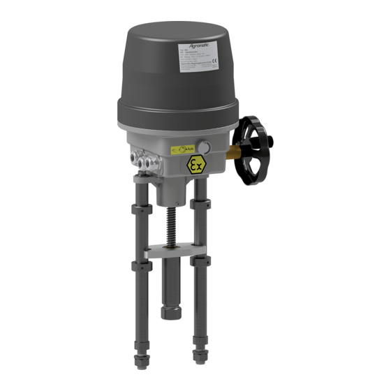
3.2 Overview 3 Product description 3.2.2 Series NEx-K, NEx-KA, NEx-V (linear actuators) Fig. 3.2: Schematic diagram series NEx, NEx-K, NEx-KA and NEx-V 1 Hood 7 Control shaft 2 Motor 8 Switch 3 Control cams 9 PCB 4 Control shaft gearbox 10 Actuator housing/Basic module 5 Handwheel 11 Mounting bracket... -
Page 25: Functional Description
3 Product description 3.3 Functional description 3.3 Functional description The actuator has been designed to operate industrial valves (e.g. dampers, ball valves, other valves) within the regulating distance determined by the mechanical characteristics of the valve. Depending on the design of the actu- ator, it is possible to move only to the valve end positions or to any position between the end positions. -
Page 26: Technical Data
3.4 Technical data 3 Product description 3.4 Technical data 3.4.1 Dimensions For details on the dimensions of the relevant series and type see section “5.2 Installation”. 3.4.2 Weight Depending on the customer-specific actuator model, however max.: NEx1 to NEx4 12 kg NEx5 and NEx6 14 kg NEx8... -
Page 27: Anti-Condensate Heater
3 Product description 3.4 Technical data DC commutator motor with permanent-magnet stator Operating voltage 24 V DC ±10 % Duty cycle: see nameplate of the actuator Important information! When stopped, the DC commutator motor does not provide a holding – torque! The DC commutator motor is not suitable for short operating periods! –... -
Page 28: Functional Data
3.4 Technical data 3 Product description 3.4.6 Functional data Torques, positioning forces, positioning ranges and positioning times NEx1 to NEx4 Torque: 5 to 60Nm Positioning times: 1.3 s/90° to 130 s/90° Turn/swivel range: max. 300 turns NEx5 and NEx6 Torque: 80 to 180 Nm Positioning times: 15 s/90°... -
Page 29: Airborne Noise Emission
3 Product description 3.4 Technical data Gearbox Maintenance-free steel spur gearing Installation position Any orientation Switch − Switch function: changeover switch (NC/NO contact) − Switching capacity: max. 6 A, 250 V AC Switches with gold-plated contacts are available for small switching loads and low voltages. -
Page 30: Nameplate
3.5 Nameplate 3 Product description 3.5 Nameplate The nameplate provides all the important technical details for the actuator. Actuator type Serial number Technical data Type examination number Each actuator can be uniquely identified by its serial number. The serial number can be found on the nameplate attached to the hood. Additional plate: Ex-marking for the flameproof enclosure IECEx EPS 15.0061X Type examination... -
Page 31: Transport And Storage
Transport and storage The actuator is shipped to the customer by a shipping agent authorized by the manufacturer. 4.1 Acceptance inspection by the receiver The actuator is shipped to the customer in a cardboard box. If required, wire-mesh boxes are used for the transport (e.g. for delivering large quantities). -
Page 32: Transport Instructions
4.3 Transport instructions 4 Transport and storage 4.3 Transport instructions NOTE Risk of damaging the actuator! Improper handling may cause the control shaft of the actuator to be bent. The control cams installed on the control shaft actuate the limit switches and the auxiliary switches. -
Page 33: Assembly
Assembly WARNING Moving components on the actuator and the valves connected to it pose a risk of injury! When the actuator is operated, the valves connected to it will also move. The threaded spindle and the spindle nut of series NEx-K und NEx-V are freely accessible. -
Page 34: General Notes
5.1 General notes 5 Assembly 5.1 General notes Important information! In order to ensure safe operation of the actuator, the device should have a rated torque that is 15-20% higher than the torque required for adjusting the valve (for rated torques refer to the section “3.4.6 Functional data” ). −... - Page 35 − Spark-quenching capacitors within the customer's power supply may in- fluence the rotational stability of the actuator and cause damages to it. − Only use original accessories from Agromatic Regelungstechnik GmbH for the actuator. WARNING Risk of injury due to fire/explosion when operating the actuator in a potentially explosive atmosphere! Improper handling may cause the control shaft of the actuator to be bent.
-
Page 36: Installation
Always observe the assembly instructions of the respective supplier when in- stalling valves and brackets. 5.2.1 Series NEx Agromatic rotary and part-turn actuators are designed for driving industrial valves (dampers, plug valves, etc.). The actuator is attached directly to the valve using four screws, or indirectly using a bracket. - Page 37 5 Assembly 5.2 Installation M6x12 Ø50 Ø6 Fig. 5.1: Series NEx1 to NEx4 A – assembly dimensions Actuators NEx, NEx-K, NEx-KA, NEx-V...
- Page 38 5.2 Installation 5 Assembly Ø90 Ø70 M8x16 M10x16 Ø35 ØD Fig. 5.2: Series NEx5 to NEx6 – assembly dimensions Actuators NEx, NEx-K, NEx-KA, NEx-V...
- Page 39 5 Assembly 5.2 Installation Fig. 5.3: Series NEx8 – assembly dimensions Actuators NEx, NEx-K, NEx-KA, NEx-V...
-
Page 40: Series Nex-K, Nex-Ka
5.2 Installation 5 Assembly 5.2.2 Series NEx-K, NEx-KA Mounting the bracket 1. Install the actuator using mounting bracket B at the prescribed position (see: Fig. 5.5 “Series NEx-K – assembly” or Fig. 5.7 “Series NEx-KA – assembly” ). Drive pin fastening 2. - Page 41 5 Assembly 5.2 Installation Series NEx-K For the dimensions of the actuator unit, see: Fig. 5.1 “Series NEx1 to NEx4 A – assembly dimensions” Fig. 5.4: Series NEx-K – assembly Fig. 5.5: Series NEx-K – assembly dimensions and radius of motion Actuators NEx, NEx-K, NEx-KA, NEx-V...
- Page 42 5.2 Installation 5 Assembly Series NEx-KA For the dimensions of the actuator unit, see: Fig. 5.1 “Series NEx1 to NEx4 A – assembly dimensions” Fig. 5.6: Series NEx-KA – assembly dimensions and radius of motion Actuators NEx, NEx-K, NEx-KA, NEx-V...
- Page 43 5 Assembly 5.2 Installation Series NEx-KA – clearances for stroke movement Type Stroke NEx-KA 150 NEx-KA 300 NEx-KA 450 NEx-KA 600 NEx-KA 750 NEx-KA 1100 1100 1185 1320 1138 Fig. 5.7: Series NEx-KA – assembly Actuators NEx, NEx-K, NEx-KA, NEx-V...
-
Page 44: Series Nex-V
5.2 Installation 5 Assembly 5.2.3 Series NEx-V For the dimensions of the actuator unit, see: Fig. 5.1 “Series NEx1 to NEx4 A – assembly dimensions” Fig. 5.8: Series NEx-V – assembly Fig. 5.9: Series NEx-V – assembly on valve dimensions Column mounting 1. - Page 45 5 Assembly 5.2 Installation 4. Installing the driving collar: − For threaded valve spindle: Screw the complete driving collar RV onto valve spindle S and secure it using grub screw GR. − For valve spindle without thread: Insert the split driving collar RG into the groove in valve spindle S 5.
-
Page 46: Assembly Of The Handwheel
5.2 Installation 5 Assembly 5.2.4 Assembly of the handwheel Fig. 5.11: Assembly of the handwheel 1. Push handwheel H onto square socket V. 2. Tighten the handwheel with washer U and screw S. Operating the handwheel see section “6.1.1 Handwheel” Actuators NEx, NEx-K, NEx-KA, NEx-V... -
Page 47: Electrical Connection
5 Assembly 5.3 Electrical connection 5.3 Electrical connection DANGER Warning of electrical hazard Working on live electrical devices poses a considerable risk of deadly or serious injuries! If an actuator is open or operational, there is a risk of coming into contact with live parts (e.g. - Page 48 5.3 Electrical connection 5 Assembly Important information! Any modification to the internal wiring is strictly forbidden! Before switching the actuator on or off, – changing any settings (e.g. rotational direction or swivel range) at the – actuator, check whether these actions could cause any dangerous movements within the machine/system or malfunctions of other assemblies! −...
-
Page 49: Determining The Direction Of Rotation
5 Assembly 5.3 Electrical connection − Protection class IP66/67 is guaranteed only if screwed cable glands are used which are approved for this protection class (see section “2.4.4 Protection classes IP66/IP67”). − Use a ring cable lug to connect the ground conductor to the screw provided for this purpose and identified by the following symbol: Important information! - Page 50 5.3 Electrical connection 5 Assembly Direction of rotation − Viewing direction through the actuator towards the output shaft (threaded spindle) − Clockwise rotation: The output shaft (threaded spindle) rotates clockwise (CW). − Counterclockwise rotation: The output shaft (threaded spindle) rotates counterclockwise (CCW). −...
- Page 51 5 Assembly 5.3 Electrical connection Fig. 5.13: NEx5 to NEx6: clockwise rotation Important information! With actuators series NEx5 and NEx6, the control shaft turns in the oppo- site direction of the output shaft (see Fig. 5.13). Actuators NEx, NEx-K, NEx-KA, NEx-V...
- Page 52 5.3 Electrical connection 5 Assembly Fig. 5.14: NEx8: clockwise rotation Actuators NEx, NEx-K, NEx-KA, NEx-V...
-
Page 53: Control Using A Bldc Motor
5 Assembly 5.3 Electrical connection 5.3.2 Control using a BLDC motor Important information! For schematic diagram, see section “5.3.4 Schematic diagram - DC (BLDC motor)”. Prerequisites for controlling the actuator − Control via programmable logic control (PLC) / logic module (provided by the customer) −... - Page 54 5.3 Electrical connection 5 Assembly Switch value table (actuator with Ex-e terminal box) Counterclock- Clockwise wise rotation Holding torque not permitted rotation CW Terminal Terminal Important information! According to the switch value tables, wires 2 and 3 or terminals 2 and 3 should not receive H potential at the same time.
- Page 55 5 Assembly 5.3 Electrical connection Right end position When the right end position is achieved, the actuator is switched off via an electromagnetic limit switch. The end position is set via the assigned control cam. Actuator with unconnected cable end: When the right end position is achieved, an H signal for evaluation purposes is provided to the customer's programmable logic controller (PLC) via wire 5 of cable 2.
-
Page 56: Control Using A Synchronous Motor
5.3 Electrical connection 5 Assembly Logic levels of the inputs and outputs The following logic levels have been specified for the individual statuses: Inputs High (H) = 24 V Low (L) Outputs High (H) = 24 V Low (L) 5.3.3 Control using a synchronous motor Important information! Schematic diagram see section “5.3.5 Schematic diagram AC (synchronous motor)”. -
Page 57: Schematic Diagram - Dc (Bldc Motor)
5 Assembly 5.3 Electrical connection 5.3.4 Schematic diagram - DC (BLDC motor) Important information! Always observe the schematic diagram attached inside the hood! Fig. 5.16: Schematic diagram BLDC motor Standard: limit switch CCW (left-hand) rotation limit switch CW (right-hand) rotation anti-condensate heater temperature switch (NC contact, can be reset manually) Options:... -
Page 58: Schematic Diagram Ac (Synchronous Motor)
5.3 Electrical connection 5 Assembly 5.3.5 Schematic diagram AC (synchronous motor) Important information! Always observe the schematic diagram attached inside the hood! Fig. 5.17: Schematic diagram Synchronous motor Standard: limit switch CCW (left-hand) rotation limit switch CW (right-hand) rotation anti-condensate heater temperature switch (NC contact, can be reset manually) Options: S1 to S4... -
Page 59: Schematic Diagram For Direct Current
5 Assembly 5.3 Electrical connection 5.3.6 Schematic diagram for direct current Counterclockwise rotation: Apply DC voltage to terminals L+ and L−. Clockwise rotation: Apply DC voltage to terminals L and L −. Fig. 5.18: DC schematic diagram 5.3.7 AC schematic diagram with service switch (option) The service switch can be used to move the actuator irrespective of the control signals present at... -
Page 60: Setting The Position Switches
5.4 Setting the position switches 5 Assembly 5.4 Setting the position switches If requested by the customer, the control cams can be factory-adjusted be- fore delivery. Important information! When starting up the travel limit switches, ensure that the valve is securely closed when the actuator has reached the relevant end position! NOTE When the end position is reached, the motor must be disconnected from... -
Page 61: Control Cam Shapes And Switches
5 Assembly 5.4 Setting the position switches 5.4.1 Control cam shapes and switches In addition to the 330° standard cam (see Fig. 5.21) other control cam shapes are available on request, e.g. the 90° cam (see Fig. 5.22). Fig. 5.21: 330° cam (left-hand: switch not activated, right-hand: switch activated) Fig. -
Page 62: Jno: Adjustable Cam To Be Set From Above
5.4 Setting the position switches 5 Assembly 5.4.2 JNO: adjustable cam to be set from above Overview Detail view of cam Fig. 5.23: Adjustable cam JNO The 4-way adjustable cam JNO is used to actuate a total of 4 position switches. - Page 63 5 Assembly 5.4 Setting the position switches Setting the travel limit switches 1. Apply the voltage for the CCW rotation (see section “5.3 Electrical con- nection” ): The output shaft rotates in counterclockwise direction. Control shaft W rotates in the same or opposite direction of the output shaft, de- pending on the actuator type (see section “5.3.1 Determining the direction of rotation” ).
-
Page 64: Jns: Sideways Adjustable Cam
5.4 Setting the position switches 5 Assembly 5.4.3 JNS: sideways adjustable cam Fig. 5.24: Sideways adjustable cam JNS The sideways adjustable cam JNS is used to operate one position switch re- spectively. On delivery, cam rests T of the individual control cams are loosely plugged onto control shaft W. - Page 65 5 Assembly 5.4 Setting the position switches Setting the travel limit switches 1. Apply the voltage for the CCW rotation (see section “5.3 Electrical con- nection” ): The output shaft rotates in counterclockwise direction. Control shaft W rotates in the same or opposite direction of the output shaft, de- pending on the actuator type (see section “5.3.1 Determining the direction of rotation” ).
-
Page 66: Brass Control Cam (Option)
5.4 Setting the position switches 5 Assembly 5.4.4 Brass control cam (option) Fig. 5.25: Brass control cam (option) The brass control cam is used for actuating one position switch at a time. On delivery, the individual control cams are loosely plugged onto control shaft W. - Page 67 5 Assembly 5.4 Setting the position switches Setting the travel limit switches 1. Apply the voltage for the CCW rotation (see section “5.3 Electrical con- nection” ): The output shaft rotates in counterclockwise direction. Control shaft W rotates in the same or opposite direction of the output shaft, de- pending on the actuator type (see section “5.3.1 Determining the direction of rotation” ).
-
Page 68: Connecting And Adjusting The Potentiometer (Option)
5.5 Connecting and adjusting the potentiometer (option) 5 Assembly 5.5 Connecting and adjusting the potentiome- ter (option) DANGER Warning of electrical hazard Working on electrical devices poses a considerable risk of deadly or seri- ous injuries! Only qualified electricians may carry out the work. –... - Page 69 5 Assembly 5.5 Connecting and adjusting the potentiometer (option) Important information! Potentiometers may only be operated as voltage dividers (see Fig. 5.26). Please refer to the schematic diagram within the hood for information on the maximum permitted wiper current i and the maximum rated power wiper of the potentiometer.
-
Page 70: 2-Wire Current Output 4
5.6 2-wire current output 4 … 20mA (option) 5 Assembly 5.6 2-wire current output 4 … 20mA (option) Electrical connection Always connect the current output with a shielded wire (minimum cross section 0.5mm², maximum length 1000m) separated from the mains voltage lines. Fig. -
Page 71: Anti-Condensate Heater
5 Assembly 5.7 Anti-condensate heater 5.7 Anti-condensate heater The anti-condensate heater is a heating resistor. This resistor is connected to the mains voltage (terminals 27 and 28, see section “5.3.5 Schematic dia- gram AC” ), to generate the heat output. The thermostatic switch activates and deactivates the anti-condensate heater when temperatures sink below 0 °C and rise above +15 °C respectively.) NOTE If the ambient temperatures vary during the assembly, the heating resistor... -
Page 72: Installing The Hood
5.8 Installing the hood 5 Assembly 5.8 Installing the hood After completing all connecting and setting work, the hood must be installed on the basic module. The following defaults must be observed during the assembly: − Before its assembly or removal, the hood must be dry so as to protect the electrical components inside the actuator against humidity. - Page 73 5.8 Installing the hood hex-nut grub screw G Fig. 5.30: Fixing of the hood Actuators NEx, NEx-K, NEx-KA, NEx-V...
-
Page 75: Operation
Operation Important information! The actuator may not be put into operation unless the owner/lessor of the machine/system has proven that the system or machine into which it is to be installed is in compliance with all applicable EC directives. The actuator may not be put into service unless the hood is properly installed, and –... - Page 76 5.8 Installing the hood 6 Operation CAUTION Danger of burning at the drive motor and at the actuator compo- nents! The drive motor may become hot during operation. The valve may transfer very low or very high temperatures to the actuator, which depend on the ambient conditions and the temperature of the medi- um flowing through the valve.
-
Page 77: Auxiliary Functions (Optional)
6 Operation 6.1 Auxiliary functions (optional) 6.1 Auxiliary functions (optional) 6.1.1 Handwheel In case of a power failure the actuator can be adjusted using a handwheel. WARNING Danger of injury from the handwheel rotating with the actuator! If the handwheel is moved while the drive motor is running, there is a risk of injury such as the upper limbs being drawn in or caught by the rotating handwheel. - Page 78 6.1 Auxiliary functions (optional) 6 Operation Fig. 6.1: Handwheel 1. Switch off the operating voltage of the actuator. 2. If a gearbox decoupling device is fitted to the actuator: Disengage the gearbox (see section “6.1.2 Gearbox decoupling” ). 3. Push handwheel H onto the stop in position M and rotate it in the desired direction.
-
Page 79: Gearbox Decoupling
6 Operation 6.1 Auxiliary functions (optional) 6.1.2 Gearbox decoupling Gearbox decoupling is required to manually moving the output shaft during the adjustment process. NOTE Risk of property damage when the gearbox is decoupled! The valve must not be twisted when the gearbox is decoupled. Decoupling cancels the holding torque of the motor, which may cause uncontrolled movements of the valve and damage the actuator gearbox. - Page 80 6.1 Auxiliary functions (optional) 6 Operation 1. Switch off the operating voltage of the actuator. 2. Remove any torque from the output shaft. 3. Turn the adjusting knob (A ) to the position M This will interrupt the torque transmission from the motor to the output shaft.
-
Page 81: Maintenance And Repair
Maintenance and repair 7.1 Safety instructions DANGER Warning of electrical hazard Working on live electrical devices poses a considerable risk of deadly or serious injuries! If an actuator is open or operational, there is a risk of coming into contact with live parts (e.g. - Page 82 7.1 Safety instructions 7 Maintenance and repair Before switching the actuator on or off, – changing any settings (e.g. rotational direction or swivel range) at the – actuator, check whether these actions could cause any dangerous movements within the machine/system or malfunctions of other assemblies! −...
-
Page 83: Maintenance Work
7 Maintenance and repair 7.2 Maintenance work 7.2 Maintenance work 7.2.1 Maintenance intervals Maintenance Maintenance task interval section Cleaning the actuator (all series) every 6 months 7.2.2 Lubricating the actuator – Series NEx – 7.2.3 every 6 months – Series NEx-K 7.2.4 –... -
Page 84: Cleaning The Actuator (All Series)
7.2 Maintenance work 7 Maintenance and repair 7.2.2 Cleaning the actuator (all series) NOTE Splash water may enter the actuator and destroy it! Use a damp cloth for cleaning. – Never clean the actuator with a high-pressure cleaner or with a water –... -
Page 85: Series Nex-K
7 Maintenance and repair 7.2 Maintenance work 7.2.4 Series NEx-K Drive motor and gear ranges The actuator is lubricated with long-life grease and therefore requires no maintenance if used as prescribed. Stroke unit NOTE Risk of damage to components due to excessively high friction! Avoid dry operation of the threaded spindle. -
Page 86: Series Nex-Ka
7.2 Maintenance work 7 Maintenance and repair 7.2.5 Series NEx-KA Drive motor and gear ranges The actuator is lubricated with long-life grease and therefore requires no maintenance if used as prescribed. Stroke unit NOTE Risk of damage to components due to excessively high friction! Avoid dry operation of the threaded spindle. -
Page 87: Series Nex-V
7 Maintenance and repair 7.2 Maintenance work 7.2.6 Series NEx-V Drive motor and gear ranges The actuator is lubricated with long-life grease and therefore requires no maintenance if used as prescribed. Stroke unit NOTE Risk of damage to components due to excessively high friction! Avoid dry operation of the threaded spindle. -
Page 88: Leak Test
− Damaged actuator housing or hood − Replace the damaged hood (see section “7.3 Spare parts” ). − If the actuator housing is damaged, return the actuator to Agromatic Regelungstechnik GmbH to have it repaired. − Heater does not work −... -
Page 89: Visual Inspection
If the cable glands, cable entries or filler plugs are damaged, please con- tact Agromatic Regelungstechnik GmbH (see section “7.3 Spare parts” ). − Are the joining elements between the actuator and the valve (e.g. screw- type connections, connecting pins) in perfect condition? Re-tighten screws, replace pins, etc. -
Page 90: Electrical Inspection (All Series)
7.2 Maintenance work 7 Maintenance and repair 7.2.10 Electrical inspection (all series) DANGER Warning of electrical hazard Working on live electrical devices poses a considerable risk of deadly or serious injuries! Only qualified and authorized electrical specialists are allowed to work –... -
Page 91: Spare Parts
7.3 Spare parts 7.3 Spare parts Only use original spare parts, as only original spare parts guarantee trouble- free function of the device. For ordering spare parts please contact: Agromatic Regelungstechnik GmbH Postfach 1162 D - 33804 Oerlinghausen Germany Phone:... -
Page 93: Malfunctions
Adhere to the regulations of the VDE and to the regulations issued by – the local utility company. 8.2 General notes Please contact our Service department if malfunctions occur with the actua- tor: Agromatic Regelungstechnik GmbH Postfach 1162 D - 33804 Oerlinghausen Germany Phone: +49 5202 9739-284... -
Page 94: Resetting The Temperature Switch
8.3 Resetting the temperature switch 8 Malfunctions 8.3 Resetting the temperature switch DANGER Risk of injury due to fire/explosion when working on explosion-proof equipment! When the hood is open, live parts may ignite an existing potentially explo- sive atmosphere and cause a fire / an explosion. Only qualified personnel should carry out work at the actuator in ac- –... - Page 95 8 Malfunctions 8.3 Resetting the temperature switch 5. Press and reset the temperature switch (1) at the basic module (see illus- tration below). Fig. 8.1: Resetting the temperature switch 6. Reinstall the hood (see section “5.8 Installing the hood”). After installing the hood, switch the actuator back on. Actuators NEx, NEx-K, NEx-KA, NEx-V...
-
Page 96: Repairs
8.4 Repairs 8 Malfunctions 8.4 Repairs Before returning an Agromatic actuator for repairs, request an RMA (“Return Material Authorization”) number from the Agromatic Regelungstechnik GmbH Service department. Agromatic Regelungstechnik GmbH Postfach 1162 D - 33804 Oerlinghausen Germany Phone: +49 5202 9739-284... -
Page 97: Decommissioning, Disassembly
Decommissioning, disassembly Only specifically trained specialists are allowed to handle decommissioning and disposal. DANGER Warning of electrical hazard Working on live electrical devices poses a considerable risk of deadly or serious injuries! If an actuator is open or operational, there is a risk of coming into contact with live parts (e.g. -
Page 98: Dismantling And Disposing Of The Actuator
− scrap metals, − Send plastics to an appropriate recycling yard − Separate other components by material and dispose of them properly Important information! You may alternatively return the actuator to Agromatic Regelungstechnik GmbH for disposal. Actuators NEx, NEx-K, NEx-KA, NEx-V... -
Page 99: Appendix
10 Appendix 10.1 Certificates The actuator complies with the following EC directives and standards: − Directive 2006/42/EC (“Machinery Directive”) − Directive 2014/34/EU (“ATEX Directive”) − Directive 2014/30/EU (“EMC Directive”) − IEC 60079-1 (Explosive atmospheres - Part 1: Equipment protection by flameproof enclosures ‘d’) On the following pages you will find −... - Page 100 10.1 Certificates 10 Appendix Actuators NEx, NEx-K, NEx-KA, NEx-V...
- Page 101 10 Appendix 10.1 Certificates Actuators NEx, NEx-K, NEx-KA, NEx-V...
- Page 102 10.1 Certificates 10 Appendix Actuators NEx, NEx-K, NEx-KA, NEx-V...
- Page 103 10 Appendix 10.1 Certificates Actuators NEx, NEx-K, NEx-KA, NEx-V...
- Page 104 10.1 Certificates 10 Appendix Actuators NEx, NEx-K, NEx-KA, NEx-V...
- Page 105 10 Appendix 10.1 Certificates Actuators NEx, NEx-K, NEx-KA, NEx-V...
- Page 106 10.1 Certificates 10 Appendix Actuators NEx, NEx-K, NEx-KA, NEx-V...
- Page 107 10 Appendix 10.1 Certificates Actuators NEx, NEx-K, NEx-KA, NEx-V...
- Page 108 10.1 Certificates 10 Appendix Actuators NEx, NEx-K, NEx-KA, NEx-V...
- Page 109 10 Appendix 10.1 Certificates Actuators NEx, NEx-K, NEx-KA, NEx-V...
-
Page 110: Index
11 Index Page numbers printed in bold indicate the section with the highest relevance. Anti-condensate heater 21, 67 Maintenance 16, 77 Assembly 29 Maintenance intervals 79 Maintenance work 79 BLDC motor 20, 49 Nameplate 24 Cams see Control cams Cleaning 79, 80 Potentially explosive area 6, 23 Control cams 57 Potentiometer 64, 66, 74, 76... - Page 112 Agromatic Regelungstechnik GmbH Postfach 1162 D - 33804 Oerlinghausen Germany Phone: +49 5202 9739-284 Fax: +49 5202 9739-25 E-Mail: sales@agromatic.de Web: www.agromatic.de...
Need help?
Do you have a question about the NEx Series and is the answer not in the manual?
Questions and answers