
Related Manuals for Agromatic NL Series


Summary of Contents for Agromatic NL Series
- Page 1 Installation and Operating Manual (Translation of the German Original) Actuator Series NL Position Controller ESR-NL (Option) Keep for future reference! Revision: 2019-06-01...
- Page 2 Legal Notice © Agromatic Regelungstechnik GmbH This operating manual and all illustrations contained therein are protected by copy- right law. Any use of the material outside the restrictions of copyright law without prior written consent from the publisher shall be prohibited and liable to legal pros- ecution.
-
Page 3: Table Of Contents
Note: An index is provided on page 87 to help you navigate to specific subjects. Contents Introduction ....................1 1.1 Notes and signs used in this document ............2 1.2 Symbols used in this manual ............... 3 1.3 Warranty and liability..................3 Safety ...................... - Page 4 Contents Transportation and storage ..............21 4.1 Acceptance inspection by the receiver ............21 4.2 Packaging, insulation .................. 21 4.3 Transport instructions ................. 22 4.4 Interim storage .................... 22 Assembly ....................23 5.1 General notes ..................... 24 5.2 Installation....................26 5.3 Electrical connection ...................
- Page 5 Contents Operation ....................65 7.1 Auxiliary functions (optional) ..............66 7.1.1 Handwheel .................... 66 7.1.2 Gearbox decoupling ................68 Maintenance and repair ................71 8.1 Safety instructions..................71 8.2 Maintenance work ..................73 8.2.1 Maintenance intervals ................73 8.2.2 Cleaning the actuator ................74 8.2.3 Leak test ....................
-
Page 7: Introduction
The following documentation in its current version should also be taken into account: − the product catalog, and − the General Terms and Conditions of Agromatic Regelungstechnik GmbH − any additional operating/installation instructions for optional accessories where applicable (e.g. electronic position controller). -
Page 8: Notes And Signs Used In This Document
1.1 Notes and signs used in this document 1 Introduction 1.1 Notes and signs used in this document Special attention should be paid to text statements in this operating manual serving as notes or direct warning of danger. Such statements are identified as shown below: DANGER Warning of dangerous electrical voltage! -
Page 9: Symbols Used In This Manual
1.3 Warranty and liability The obligations laid down in the supply contract, the General Terms and Conditions, the delivery terms of Agromatic Regelungstechnik GmbH and the legal regulations in force at the time of the signing of the contract shall apply. - Page 10 Important information regarding the EC conformity of the actuator The declaration of conformity and or declaration of incorporation issued by Agromatic Regelungstechnik GmbH shall become void if the customer performs structural or technical modifications to the actuator. In this case,...
-
Page 11: Safety
Safety WARNING Failure to observe the safety instructions below may have serious consequences: Danger to persons from electrical or mechanical influences – Failure of essential functions – Carefully read the safety instructions and hazard warnings in this section before commissioning the actuator. Observe the general safety instructions and regulations for the prevention of accidents in addition to the instructions in this operating manual. -
Page 12: Intended Use
Any use of the actuator other than the intended use described in this docu- ment shall not be permitted and will be regarded as misuse. Agromatic Regelungstechnik GmbH shall not accept liability for any damage resulting from such misuse. The owner/lessor shall bear the sole risk for pos- sible damage due to improper use. -
Page 13: Hazards From Electrical Energy
2 Safety 2.3 Residual risks 2.3.1 Hazards from electrical energy DANGER Warning of dangerous electrical voltage! Direct contact with live parts or with parts that became energized due to faults poses an immediate threat to life. Damage to the insulation or to individual components may be life-threatening. -
Page 14: Danger From Moving Parts
2.3 Residual risks 2 Safety 2.3.2 Danger from moving parts WARNING Moving components on the actuator and the valves connected to it pose a risk of injury! When the actuator is operated, the valves connected to it will also move. When couplings are used between the actuator and the valve, there is a risk of injury due to moving parts. -
Page 15: Protection Classes Ip65 (Standard), Ip66 (Option)
Outdoor installation of the actuator is only permitted if approved by – Agromatic Regelungstechnik GmbH. Protect the actuator against environmental influences such as UV radia- – tion, humidity, formation of condensation, fluctuations of temperature, and frost. -
Page 16: Personal Protective Equipment
2.4 Personal protective equipment 2 Safety 2.4 Personal protective equipment Personal protective equipment must be worn when starting up and operating the actuator to minimize exposure to a variety of hazards. − When working, always wear protective equipment that is required for the kind of work being carried out. -
Page 17: Notes For Emergencies
2 Safety 2.5 Notes for emergencies 2.5 Notes for emergencies Preventive measures − Always be prepared for accidents or fires. − Keep the first aid equipment (first aid kit, blankets, etc.) and fire extin- guishing substances close at hand. − Have the personnel instructed in the proper use of accident reporting, first aid, fire extinguishing and rescue equipment. -
Page 18: Obligations Of The Owner/Lessor
2.6 Obligations of the owner/lessor 2 Safety 2.6 Obligations of the owner/lessor The actuator is designed for industrial use. The owner/lessor of the actuator is therefore legally obligated to maintain safety at work. In addition to the safety instructions provided in this operating manual, the safety instructions, instructions for the prevention of accidents and the envi- ronmental legislation in effect at the area of use of the actuator must be com- plied with. -
Page 19: Requirements Imposed On The Personnel
2 Safety 2.7 Requirements imposed on the personnel 2.7 Requirements imposed on the personnel The actuator may be operated and serviced only by personnel that have been trained, instructed and authorized for this purpose. Such persons must know the operating manual and act according to it. The employees' responsi- bilities must be clearly defined. -
Page 20: Qualifications Required Of The Personnel
2.7 Requirements imposed on the personnel 2 Safety 2.7.2 Qualifications required of the personnel WARNING Danger of injury in case of insufficient qualification! Improper handling can result in serious personal injury. Therefore, ensure that all tasks are carried out only by appropriately quali- fied personnel. -
Page 21: Product Description
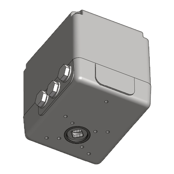
Product description 3.1 Product series The actuator is available in two product series: Rotary and part-turn actuator (8 to 40Nm) NL with additional gearbox: Rotary and part-turn actuator (60 to 120Nm) 3.2 Overview 1 Hood 2 Motor 3 Gearbox decoupling 4 Actuator housing 5 Output shaft 6 Switch... -
Page 22: Functional Description
3.3 Functional description 3 Product description 3.3 Functional description The actuator has been designed to operate industrial valves (e.g. dampers, ball valves, other valves) within the positioning range determined by the me- chanical characteristics of the valve. Depending on the design of the actua- tor, it is possible to move only to the valve end positions or to any position be- tween the end positions. -
Page 23: Actuator Motor
3 Product description 3.4 Technical data 3.4.4 Actuator motor Alternating current Important information! Frequency fluctuations affect the positioning time of the device. Synchronous motor with permanent-magnet rotor 230V AC ±10%, 50/60Hz ±5% 115V AC ±10%, 50/60Hz ±5% Duty cycle: see nameplate of the actuator NOTE The specified voltage range of ±10% must always be maintained! –... -
Page 24: Airborne Noise Emission
3.4 Technical data 3 Product description Gearbox Maintenance-free steel spur gearing Installation position Any orientation Switch − Switch function: changeover switch (NC/NO contact) − Switching capacity: max. 6A, 250V AC Switches with gold-plated contacts are available for small switching loads and low voltages. -
Page 25: Nameplate
18 VA (AC) 230 V 50/60 Hz data 90° 25(21) s 10 Nm -15/+60 °C IP 54 ESR-N 4-20 mA Baujahr/Year Built: 2013 Options Agromatic Regelungstechnik GmbH Stukenbrocker Weg 38 +49 5202 9739-284 33813 Oerlinghausen www.agromatic.de Made in Deutschland Germany Every actuator is clearly identified by its serial number. -
Page 27: Transportation And Storage
Transportation and storage The actuator is shipped to the customer by a shipping agent authorized by the manufacturer. 4.1 Acceptance inspection by the receiver The actuator is shipped to the customer in a cardboard box. If required, wire-mesh boxes are used for the transport (e.g. for delivering large quantities). -
Page 28: Transport Instructions
4.3 Transport instructions 4 Transportation and storage 4.3 Transport instructions NOTE Risk of damaging the actuator! Improper handling may cause the control shaft of the actuator to be bent. The control cams installed on the control shaft actuate the limit switches and the auxiliary switches. -
Page 29: Assembly
Assembly WARNING Moving components on the actuator and the valves connected to it pose a risk of injury! When the actuator is operated, the valves connected to it will also move. When couplings are used between the actuator and the valve, there is a risk of injury due to moving parts. -
Page 30: General Notes
5.1 General notes 5 Assembly 5.1 General notes Important information! In order to ensure safe operation of the actuator, the device should have a rated torque that is 15-20% higher than the torque required for adjusting the valve (for rated torques see section “3.4.5 Functional data” ). −... - Page 31 − Spark-quenching capacitors within the customer's power supply may in- fluence the rotational stability of the actuator and cause damages to it. − Only use original accessories from Agromatic Regelungstechnik GmbH for the actuator. NOTE Risk of damaging the actuator! Improper handling may cause the control shaft of the actuator to be bent.
-
Page 32: Installation
5.2 Installation 5 Assembly 5.2 Installation Agromatic rotary and part-turn actuators are designed for driving industrial valves (dampers, plug valves, etc.). The actuator is installed either using a bracket and 4 screws or an adapter but can also be attached directly to the valve if required. Also be sure to fol- low the instructions in Fig. - Page 33 5 Assembly 5.2 Installation M6 x 12 deep Fig. 5.1: Series NL – assembly dimensions Actuator NL, Position Controller ESR-NL...
- Page 34 5.2 Installation 5 Assembly M10 x 16 deep M8 x 16 deep Square WAF17 Fig. 5.2: Series NL with additional gearbox – assembly dimensions Actuator NL, Position Controller ESR-NL...
-
Page 35: Electrical Connection
5 Assembly 5.3 Electrical connection 5.3 Electrical connection DANGER Warning of dangerous electrical voltage! Working on live electrical devices poses a considerable risk of deadly or serious injuries! If an actuator is open or operational, there is a risk of coming into contact with live parts (e.g. - Page 36 5.3 Electrical connection 5 Assembly − Check whether the type of current, mains voltage and mains frequency match the motor specifications. Refer to the nameplates on the hood and located inside the actuator. − The power cord must be sized to suit the maximum power consumption of the actuator.
-
Page 37: Determining The Direction Of Rotation
5 Assembly 5.3 Electrical connection 5.3.1 Determining the direction of rotation Initial connection of the actuator: Make sure that the connected valve is approx. in the center of its posi- – tioning range. Check the direction of rotation. – Direction of rotation −... - Page 38 5.3 Electrical connection 5 Assembly Fig. 5.4: NL with additional gearbox – right-hand rotation, clockwise Important information! With actuators series N5 and N6, the control shaft turns in the opposite direction of the output shaft (see Fig. 5.4). Actuator NL, Position Controller ESR-NL...
- Page 39 5 Assembly 5.3 Electrical connection Fig. 5.5: PCB NL-Basic (design example) Left-hand rotation − If mains voltage is applied between terminal N and 2, the output shaft ro- tates in left-hand direction (CCW). − This direction of rotation is limited by switch SL. −...
-
Page 40: Schematic Diagram For Alternating Current
5.3 Electrical connection 5 Assembly 5.3.2 Schematic diagram for alternating current Important information! Always observe the schematic diagram attached inside the hood! Standard Options Fig. 5.6: Schematic diagram for alternating current Standard: limit switch CCW (left-hand) rotation limit switch CW (right-hand) rotation Options: S1, S2 auxiliary switch 1, auxiliary switch 2... -
Page 41: Ac Schematic Diagram With Service Switch (Option)
5 Assembly 5.3 Electrical connection 5.3.3 AC schematic diagram with service switch (option) The service switch can be used to move the actuator irrespective of the control signals present at terminals 2 and 3. Hand = manual operation Rechts = right-hand operation (CW rotation) Links = left-hand operation (CCW rotation) -
Page 42: Setting The Position Switches
5.4 Setting the position switches 5 Assembly 5.4 Setting the position switches If requested by the customer, the control cams can be factory-adjusted be- fore delivery. Important information! When moving to the end positions given by the position limit switches, ensure that the valve is securely closed when the actuator has reached the relevant end position! NOTE... -
Page 43: Control Cam Shapes And Switches
5 Assembly 5.4 Setting the position switches 5.4.1 Control cam shapes and switches In addition to the 330° standard cam (see Fig. 5.9) other control cam shapes are available on request, e.g. the 180° cam (see Fig. 5.10). Fig. 5.9: 330° cam (left-hand: switch not activated, right-hand: switch activated) Fig. -
Page 44: Plastic Control Cam (Standard)
5.4 Setting the position switches 5 Assembly 5.4.2 Plastic control cam (standard) Fig. 5.11: Plastic control cam The plastic control cam is used to actuate one position switch at a time. The individual control cams are secured to the control shaft using an integrated O-ring and can be rotated by hand. - Page 45 5 Assembly 5.4 Setting the position switches Setting the position limit switches 1. Apply the voltage for CCW rotation (see section “5.3 Electrical connec- tion” ): The output shaft rotates in counterclockwise direction. Control shaft W rotates in the same or opposite direction of the output shaft, de- pending on the actuator type (see section “5.3.1 Determining the direction of rotation”...
-
Page 46: Aluminum Control Cam (Option)
5.4 Setting the position switches 5 Assembly 5.4.3 Aluminum control cam (option) Fig. 5.12: Aluminum control cam (option) The aluminum control cam is used for actuating one position switch at a time. On delivery the individual control cams are loosely plugged onto the control shaft W. - Page 47 5 Assembly 5.4 Setting the position switches Setting the position limit switches 1. Apply the voltage for CCW rotation (see section “5.3 Electrical connec- tion” ): The output shaft rotates in counterclockwise direction. Control shaft W rotates in the same or opposite direction of the output shaft, de- pending on the actuator type (see section “5.3.1 Determining the direction of rotation”...
-
Page 48: Threaded Sleeve For A Large Positioning Range (Option)
5.4 Setting the position switches 5 Assembly 5.4.4 Threaded sleeve for a large positioning range (option) Fig. 5.13: Threaded sleeve for a large positioning range > 330° (option) Threaded plate B on threaded sleeve H actuates the two limit switches SL and SR. - Page 49 5 Assembly 5.4 Setting the position switches Setting the position limit switches 1. Apply the voltage for CCW rotation (see section “5.3 Electrical connec- tion” ): The output shaft rotates in counterclockwise direction. Control shaft W rotates in the same or opposite direction of the output shaft, de- pending on the actuator type (see section “5.3.1 Determining the direction of rotation”...
-
Page 50: Connecting And Adjusting The Potentiometer (Option)
5.5 Connecting and adjusting the potentiometer (option) 5 Assembly 5.5 Connecting and adjusting the potentiome- ter (option) DANGER Warning of dangerous electrical voltage! Working on electrical devices poses a considerable risk of deadly or seri- ous injuries! Only qualified electricians may carry out the work. –... - Page 51 5 Assembly 5.5 Connecting and adjusting the potentiometer (option) Important information! Potentiometers may only be operated as voltage dividers (see Fig. 5.14). Please refer to the schematic diagram inside the hood for information on the maximum permitted wiper current i and the maximum rated power wiper of the potentiometer.
-
Page 52: 2-Wire Current Output 4 C 20Ma (Option)
5.6 2-wire current output 4 C 20mA (option) 5 Assembly 5.6 2-wire current output 4 D 20mA (option) Electrical connection Always connect the current output with a shielded wire (minimum cross-section 0.5mm², maximum length 1000m) separated from the mains voltage lines. Fig. -
Page 53: Anti-Condensate Heater (Option)
5 Assembly 5.7 Anti-condensate heater (option) 5.7 Anti-condensate heater (option) The anti-condensate heater is a heating resistor. This resistor is connected to the mains voltage (terminals 27 and 28, see section “5.3.2 Schematic dia- gram for alternating current” ) to generate the heat output. NOTE If the ambient temperature varies during the installation, the heating resis- tor must be connected immediately to the voltage supply and remain con-... -
Page 55: Electronic Position Controller Esr-Nl (Option)
Electronic position controller ESR-NL (option) 6.1 Description The electronic position controller series ESR-NL integrated into the actuator housing has been designed to regulate the angle position of the actuator based on a setpoint specification. A potentiometer is used as an actual value encoder. -
Page 56: Electrical Connection
6.2 Electrical connection 6 Electronic position controller ESR-NL (option) 6.2 Electrical connection Depending on the applied setpoint and the position of the actuator, the position controller starts to move the actuator immediately after the operat- ing voltage has been switched on. This may cause possibly dangerous movements of the actuated valve. - Page 57 6 Electronic position controller ESR-NL (option) 6.2 Electrical connection Before switching the actuator on or off, – changing any settings (e.g. rotational direction or swivel range) at the – actuator, check whether these actions could cause any dangerous movements within the machine/system or malfunctions of other assemblies! −...
-
Page 58: Schematic Diagram
6.2 Electrical connection 6 Electronic position controller ESR-NL (option) 6.2.1 Schematic diagram Fig. 6.1: Schematic diagram ESR-NL Standard: motor of the actuator ESR-NL electronic position controller limit switch CCW (left-hand) rotation limit switch CW (right-hand) rotation 51, 52 setpoint input 54, 55 actual value output Options:... -
Page 59: Controls And Indicators
6 Electronic position controller ESR-NL (option) 6.2 Electrical connection 6.2.2 Controls and indicators Fig. 6.2: PCB ESR-NL (design example) motor terminal mains voltage terminal terminal for setpoint and actual value buttons for operating the position controller Sliding switch Auto/Manu two-color LED indicating the status gearwheel on control shaft gearwheel on potentiometer shaft Actuator NL, Position Controller ESR-NL... - Page 60 6.2 Electrical connection 6 Electronic position controller ESR-NL (option) Indicator LEDs 1 = green LED 2 = red LED Controls Sliding switch Auto/Manu Auto = automatic mode Manu = manual mode Button block Button L manual mode, CCW rotation Button MENU programming mode Button R manual mode, CW rotation...
-
Page 61: Depiction Of The Button, Switch And Led Statuses
6 Electronic position controller ESR-NL (option) 6.2 Electrical connection 6.2.3 Depiction of the button, switch and LED statuses No button pressed Button MENU pressed Sliding switches Auto/Manu in position Auto Sliding switches Auto/Manu in position Manu Green LED off Red LED off Green LED, slowly flashing Red LED off Green LED, quickly flashing... -
Page 62: Setting The Limit Switches And The Potentiometer
6.2 Electrical connection 6 Electronic position controller ESR-NL (option) 6.2.4 Setting the limit switches and the potentiometer Before the limit switches are adjusted, – the potentiometer is adjusted, – the sliding switch Auto/Manu must be set to the position OFF = manual mode! Setting the position limit switches For details on how to adjust the position limit switches, also see section “5.4 Setting the position switches”. -
Page 63: Setpoint Value Input And Actual Value Output
6 Electronic position controller ESR-NL (option) 6.2 Electrical connection 6.2.5 Setpoint value input and actual value output The ESR-NL is delivered in one of 4 versions according to the order: Version Setpoint Actual value 1 (standard) 0(4) C 20mA 0(4) C 20mA 0(2) C 10V 0(2) C 10V 0(4) C 20mA... -
Page 64: Programming
6.2 Electrical connection 6 Electronic position controller ESR-NL (option) 6.2.6 Programming The programming procedure is used to assign the setpoints 0(4)mA and 20mA (or 0(2) V and 10 V) to the two end positions of the positioning range. The setpoint can also be freely assigned in the range of 0 C 20mA (see also page 59 “Selecting the setpoint for the left end position”... - Page 65 6 Electronic position controller ESR-NL (option) 6.2 Electrical connection Programming the left end position Move to the left end position by press- ing button L. If the end position is overrun, the actuator must be moved far enough in reverse direc- tion using button R.
- Page 66 6.2 Electrical connection 6 Electronic position controller ESR-NL (option) Programming the right end position Move to the right end position by press- ing button R. If the end position is overrun, the actuator must be moved far enough in reverse direc- tion using button L.
- Page 67 6 Electronic position controller ESR-NL (option) 6.2 Electrical connection Setting the actual value range 0 D 20mA or 4 D 20 mA 10. Select the actual value range for the right end position by pressing button L several times (if required). ►...
-
Page 68: Resetting The Controller Programming
6.2 Electrical connection 6 Electronic position controller ESR-NL (option) 6.2.7 Resetting the controller programming Resetting the controller programming (“Reset”) deletes all the parameters stored when programming the position controller. After a reset the position controller must be programmed again (see section “6.2.6 Programming” ). Before the position controller can be reset, sliding switch Auto/Manu must be set to the position Manu = manual operation! -
Page 69: Led Status Indicator
6 Electronic position controller ESR-NL (option) 6.2 Electrical connection 6.2.8 LED status indicator Indicator LEDs 1 = green LED 2 = red LED If operating voltage is applied Mode Button Function Setpoint Green LED Red LED Manu – – Move actuator Manu clockwise Move actuator... -
Page 70: Technical Data Esr-Nl
6.3 Technical data ESR-NL 6 Electronic position controller ESR-NL (option) 6.3 Technical data ESR-NL Operating voltage 230V AC ±10%, 50/60Hz ±5% 115V AC ±10%, 50/60Hz ±5% Setpoint input − Current input: 0(4) C 20mA internal burden resistor: 250Ω − overload protection 25mA −... -
Page 71: Operation
Operation Important information! The actuator may not be put into operation unless the owner/lessor of the machine/system has proven that the system or machine into which it is to be installed is in compliance with all applicable EC directives. The actuator may not be put into service unless the hood is properly installed, and –... -
Page 72: Auxiliary Functions (Optional)
7.1 Auxiliary functions (optional) 7 Operation Important information! Make manual settings on the actuator only at the output shaft end – where required. Do not rotate the control shaft! – As an alternative, you can also install auxiliary functions to the actuator –... - Page 73 7 Operation 7.1 Auxiliary functions (optional) Fig. 7.1: Handwheel 1. Switch off the operating voltage of the actuator. 2. Push handwheel H onto the stop in position M and rotate it in the desired direction. Hold the handwheel in position M while rotating it. The control cams and the potentiometer shaft also rotate in manual operation.
-
Page 74: Gearbox Decoupling
7.1 Auxiliary functions (optional) 7 Operation 7.1.2 Gearbox decoupling Decoupling the gearbox is possible necessary for manually moving the output shaft during the adjustment process. NOTE Risk of property damage when the gearbox is decoupled! The valve must not be tensioned when the gearbox is decoupled. Decou- pling cancels the holding torque of the motor, which may cause uncon- trolled movements of the valve and damage the actuator gearbox. - Page 75 7 Operation 7.1 Auxiliary functions (optional) Fig. 7.2: Gearbox decoupling knob 1. Switch off the operating voltage of the actuator. 2. Remove any torque from the output shaft. 3. Push knob G onto the stop and hold it in this position. This will interrupt the torque transmission from the motor to the output −...
-
Page 77: Maintenance And Repair
Maintenance and repair 8.1 Safety instructions DANGER Warning of dangerous electrical voltage! Working on live electrical devices poses a considerable risk of deadly or serious injuries! If an actuator is open or operational, there is a risk of coming into contact with live parts (e.g. - Page 78 8.1 Safety instructions 8 Maintenance and repair − Inform the operating staff before starting any maintenance and inspection work. − Before carrying out any maintenance or inspection work, always discon- nect the actuator from the power supply using the disconnecting device provided by the owner/lessor and protect the disconnecting device against being switched on unexpectedly.
-
Page 79: Maintenance Work
8 Maintenance and repair 8.2 Maintenance work 8.2 Maintenance work 8.2.1 Maintenance intervals Maintenance Maintenance task interval section Cleaning the actuator every 6 months 8.2.2 Checking for leakage every 6 months 8.2.3 Visual inspection once per year 8.2.4 2) 3) Electrical inspection every 4 years 8.2.5... -
Page 80: Cleaning The Actuator
8.2 Maintenance work 8 Maintenance and repair 8.2.2 Cleaning the actuator NOTE Splash water may enter the actuator and destroy it! Use a damp cloth for cleaning. – Never clean the actuator with a high-pressure cleaner or with a water –... -
Page 81: Leak Test
− Damaged actuator housing or hood − Replace the damaged hood (see section “8.3 Spare parts” ). − If the actuator housing is damaged, return the actuator to Agromatic Regelungstechnik GmbH to have it repaired. − Heater does not work −... -
Page 82: Visual Inspection
8.2 Maintenance work 8 Maintenance and repair 8.2.4 Visual inspection An initial visual inspection must be carried out 6 months after start-up, after which the inspection should be repeated at one-year intervals. The following should be verified: − Are the fastening screws between the part-turn actuator and the valve firmly tightened? Re-tighten screws if required. -
Page 83: Spare Parts
8.3 Spare parts 8.3 Spare parts Only use original spare parts, as only original spare parts guarantee trouble- free function of the device. For ordering spare parts please contact: Agromatic Regelungstechnik GmbH Postfach 1162 33804 Oerlinghausen Germany Phone: +49 5202 9739-284... -
Page 85: Malfunctions
Electronic and Information Technologies) and to the regulations is- sued by the local utility company. 9.2 General notes Please contact our Service department if malfunctions occur with the actua- tor: Agromatic Regelungstechnik GmbH Postfach 1162 33804 Oerlinghausen Germany Phone:... -
Page 86: Repairs
9.3 Repairs 9 Malfunctions 9.3 Repairs Before returning an Agromatic actuator for repairs, request an RMA (“Return Material Authorization”) number from the Agromatic Regelungstechnik GmbH Service department. Agromatic Regelungstechnik GmbH Postfach 1162 33804 Oerlinghausen Germany Phone: +49 5202 9739-284 Fax:... -
Page 87: Decommissioning, Disassembly
10 Decommissioning, disassembly Only specifically trained technical staff may carry out the decommissioning and/or disposal of the product. DANGER Warning of dangerous electrical voltage! Working on live electrical devices poses a considerable risk of deadly or serious injuries! If an actuator is open or operational, there is a risk of coming into contact with live parts (e.g. -
Page 88: Dismantling And Disposing Of The Actuator
− Transfer the dismantled components to the recycling process: − scrap metals, − send plastic elements to recycling, − dispose of other components segregated by material type. Important information! You may alternatively return the actuator to Agromatic Regelungstechnik GmbH for disposal. Actuator NL, Position Controller ESR-NL... -
Page 89: Appendix
11 Appendix 11.1 Certificates The actuator complies with the following EC directives: − Directive 2006/42/EC (“Machinery Directive”) − Directive 2014/30/EU (“EMC Directive”) On the following pages you will find translations of the German − declaration of incorporation for a partly completed machine according to Annex II, part 1, section B of the directive 2006/42/EC for rotary and part- turn actuators −... - Page 90 11.1 Certificates 11 Appendix Actuator NL, Position Controller ESR-NL...
- Page 91 11 Appendix 11.1 Certificates Actuator NL, Position Controller ESR-NL...
- Page 92 11.1 Certificates 11 Appendix Actuator NL, Position Controller ESR-NL...
-
Page 93: Index
12 Index Page numbers printed in bold indicate the section with the highest relevance. assembly 23 repairs 80 resetting the position controller 62 RoHS 86 cam see control cam cleaning 73, 74 control cam 37 schematic diagram - aluminum control cam 40 - alternating current 34 - plastic control cam 38 - current output 46... - Page 94 Agromatic Regelungstechnik GmbH Postfach 1162 33804 Oerlinghausen Deutschland Phone: +49 5202 9739-284 Fax: +49 5202 9739-25 E-Mail: sales@agromatic.de Web: www.agromatic.de...
Need help?
Do you have a question about the NL Series and is the answer not in the manual?
Questions and answers