
Related Manuals for Infra Cool CMS-03-S

Summary of Contents for Infra Cool CMS-03-S
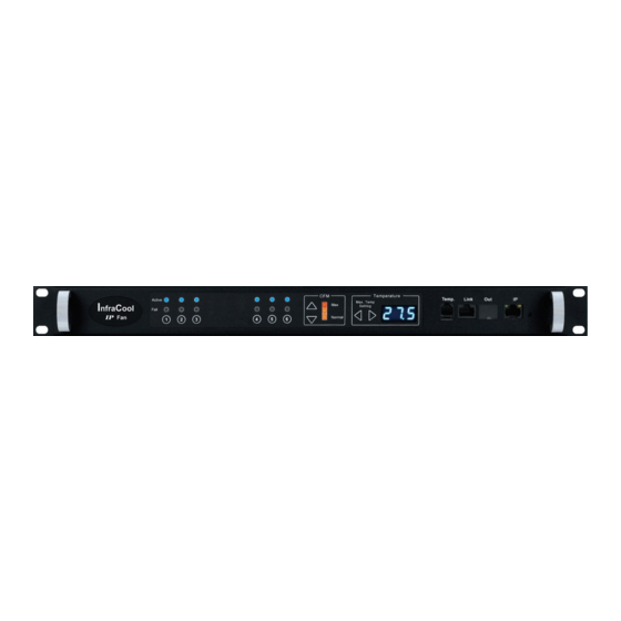
- Page 1 Rack Airfl ow Control User Manual CMS-03-S , Master IP Fan unit GUI & SNMP Designed and manufactured by Austin Hughes UM-CMS-03-S-Q421V2 www.austin-hughes.com...
- Page 2 ■ Re-position or relocate the receiving antenna. ■ Increase the separation between the equipment and receiver. ■ Connect the equipment into an outlet on a circuit diff erent from that to which the receiver is connected. UM-CMS-03-S-Q421V2 www.austin-hughes.com...
- Page 3 Unpacking The equipment comes with the standard parts shown on the package contents. Check and make sure they are included and in good condition. If anything is missing, or damage, contact the supplier immediately. UM-CMS-03-S-Q421V2 www.austin-hughes.com...
- Page 4 RF-33.9 ( 33U Door Mount Fan Panel with 9 fans ) Specifi cation Table < 2.5 > Daisy Chain Connection < 2.6 > Audio Temperature Alarm Setting < 2.7 > Temperature Sensor < 2.8 > Alarm Temperature Setting < 2.9 > Fan Unit CFM Setting UM-CMS-03-S-Q421V2 www.austin-hughes.com...
- Page 5 P.21 < 3.1 > Key Features < 3.2 > Master IP Confi guration < 3.3 > CMS-03-S Master IP Fan Unit GUI < 3.4 > SNMP Setup < 3.5 > Master IP Fan Unit Firmware Upgrade < 3.6 > DHCP Setting UM-CMS-03-S-Q421V2 www.austin-hughes.com...
-
Page 6: Package Content
- 6 ft power cord x 1 pc - Rear mounting bracket x 1 pair * M6 screws for fi xing are not included Installation MRF-1.6 / RF-1.6 Rear mounting M6 screws brackets MRF-1.9 / RF-1.9 M6 screws Rear mounting brackets UM-CMS-03-S-Q421V2 www.austin-hughes.com... - Page 7 - M4*6mm screw with nut x 4 sets - Mounting screw x 6 pcs ( attached with the unit ) - M4*10mm screw x 2 pcs - Air blocking material x 1 pc * For installation, please refer to p.5 UM-CMS-03-S-Q421V2 www.austin-hughes.com...
-
Page 8: Installation Steps
If no cable entry on the top, the unit may be installed on the inside but the model need to be changed. Please refer to P.2 . Use cable clip to hold the power cord if necessary Power cord Mounting Cable screws clip ON / OFF Button Perforated Rack Door UM-CMS-03-S-Q421V2 www.austin-hughes.com... - Page 9 Ensure all open perforations are covered by the material. Fix the air blocking material with magnets or double sided adhesive tapes Magnets & adhesive tapes not provided Perforated Rack Door UM-CMS-03-S-Q421V2 www.austin-hughes.com...
-
Page 10: Hanging Bracket Installation
Place attached 4 screws then through the door and tighten them. Follow steps on P.3 and P.4 . Power cord Cable clip ON / OFF Hanging bracket with Button M4*6mm screw & nut M4*10mm screws Mounting screws Perforated Rack Door UM-CMS-03-S-Q421V2 www.austin-hughes.com... - Page 11 - Unit CFM ( fan speed ) Setting - Temperature LED - Fan Status LED - CFM Status LED 1U Fan Tray 6 / 9 fans 6 / 9 fans Door Mount Fan Panel 9 fans 9 fans UM-CMS-03-S-Q421V2 www.austin-hughes.com...
- Page 12 Air Delivery : 108 CFM Rated Speed : 3000 rpm, +/-10% Rated Voltage : 12V DC Rated Current : 350 mA Noise Level : 41 dB Dimension : 120 x 120 x 25 mm Bearing System : Dual ball bearing UM-CMS-03-S-Q421V2 www.austin-hughes.com...
- Page 13 - 1 x IP port allows access to 16 levels - Press the reset button and release instantly to reboot build-in IP dongle - Press and hold the reset button until Orange LED off to reset build-in IP dongle to factory default UM-CMS-03-S-Q421V2 www.austin-hughes.com...
- Page 14 - 1 x IP port allows access to 16 levels - Press the reset button and release instantly to reboot build-in IP dongle - Press and hold the reset button until Orange LED off to reset build-in IP dongle to factory default unit : mm UM-CMS-03-S-Q421V2 www.austin-hughes.com...
- Page 15 Orange LED off to reset build-in IP dongle to factory default - Individual fan status - Individual fan On / Off buttons - Unit CFM Status LED - Unit CFM ( fan speed ) Setting - Buttons for Alarm Temp. Setting UM-CMS-03-S-Q421V2 P.10 www.austin-hughes.com...
- Page 16 8 kgs / 17.6 lbs MRF-1.9 9 kgs / 19.8 lbs 11 kgs / 24.2 lbs MRF-33.9 5 kgs / 11 lbs 7.4 kgs / 16.3 lbs Casing Color Black Regulatory FCC & CE Environmental RoHS3 & REACH compliant by SGS UM-CMS-03-S-Q421V2 P.11 www.austin-hughes.com...
- Page 17 - Temp. port bundled w/ a temp. sensor - Daisy chain Link port for connecting to the Out port of the 2nd level fan unit - Daisy chain Out port for connecting to the Link port of the next level fan unit UM-CMS-03-S-Q421V2 P.12 www.austin-hughes.com...
- Page 18 - Temp. port bundled w/ a temp. sensor - Daisy chain Link port for connecting to the Out port of the 2nd level fan unit - Daisy chain Out port for connecting to the Link port of the next level fan unit UM-CMS-03-S-Q421V2 P.13 www.austin-hughes.com...
- Page 19 Link port of the next level fan unit - Individual fan status - Individual fan On / Off buttons - Unit CFM Status LED - Unit CFM ( fan speed ) Setting - Buttons for Alarm Temp. Setting UM-CMS-03-S-Q421V2 P.14 www.austin-hughes.com...
- Page 20 8 kgs / 17.6 lbs RF-1.9 9 kgs / 19.8 lbs 11 kgs / 24.2 lbs RF-33.9 5 kgs / 11 lbs 7.4 kgs / 16.3 lbs Casing Color Black Regulatory FCC & CE Environmental RoHS3 & REACH compliant by SGS UM-CMS-03-S-Q421V2 P.15 www.austin-hughes.com...
-
Page 21: Daisy Chain Connection
Please follow the steps below the set the daisy chain level for Master IP Fan unit & expansion fan units ■ For the cabling connection, please refer to next page. Step 1. Press and hold the “ “ button for 5 seconds. Step 2. Press arrow button to set the daisy chain level UM-CMS-03-S-Q421V2 P.16 www.austin-hughes.com... - Page 22 Link Link Cat5 / 6 cable Cat5 / 6 cable max. 20 meters max. 20 meters To Link port of next level Expansion Serial Fan Unit (max level: 16) To Network Device for IP Access via WAN UM-CMS-03-S-Q421V2 P.17 www.austin-hughes.com...
-
Page 23: Temperature Sensor
Part no. : IG - T01 - 2M - Plug & Play - External sensor with 2M cord - Low profi le design with magnetic base for easy affi xing to the rack Optional 4M cord for Temp. Sensor UM-CMS-03-S-Q421V2 P.18 www.austin-hughes.com... - Page 24 4-wired 3.5mm to RJ11 cable ( 2m, black color ) Compatibility InfraPower W / WS / Wi / WSi series PDU InfraSolution X-2000 series InfraGuard EC-300M & EC-300 Safety Regulatory FCC & CE certifi ed Environmental RoHS3 & REACH compliant UM-CMS-03-S-Q421V2 P.19 www.austin-hughes.com...
-
Page 25: Alarm Temperature Setting
CFM setting. However, if the outside temperature is over alarm temperature, the unit CFM will be automatically changed to Max. level. Under this condition, all fan kits will be turned on. UM-CMS-03-S-Q421V2 P.20 www.austin-hughes.com... -
Page 26: Key Features
< 3.1 > Key Features InfraCool Manager CMS-03-S is a FREE built-in GUI of each Master IP Fan unit to remotely monitor the connected Expansion Serial Fan units. ( max. up to 16 fan units ) InfraCool Manager CMS-03-S Features... - Page 27 10. Change the desired IP address / Subnet mask / Gateway, then click Save to confi rm the setting to Master IP fan unit. 11. The default IP address is as below: IP address : 192.168.0.1 Subnet mask : 255.255.255.0 Gateway : 192.168.0.254 UM-CMS-03-S-Q421V2 P.22 www.austin-hughes.com...
- Page 28 < 3.3 > CMS-03-S Master IP Fan Unit GUI Each Master IP Fan Unit provides a FREE built-in GUI, CMS-03-S, which allows user, via a web browser, to see and manage the Intelligent Fan Unit’s data remotely over a TCP / IP Ethernet network.
- Page 29 < 3.3 > CMS-03-S Master IP Fan Unit GUI In < Details >, - Change “ Rack “ and “ Position “ of Fan Unit and Click “ Apply “ to fi nish the settings. - Switch ON / OFF Fan Unit...
- Page 30 < 3.3 > CMS-03-S Master IP Fan Unit GUI In < Temp. Setting >, - “ Activate “ or “ Deactivate “ Temp. sensor - Change “ Location “ , “ Alarm Setting “ & “ R. alert setting “ of Temp. sensor - “...
- Page 31 < 3.3 > CMS-03-S Master IP Fan Unit GUI In < System >, - Change Master IP Fan Unit name & location - Change temperature unit displayed in UI - Set the “ Date & Time “ of the Master IP Fan unit ( by “ Manually “ or “ NTP server “ ).
- Page 32 < 3.3 > CMS-03-S Master IP Fan Unit GUI In < Network >, you can view the current IP setting of Master IP Fan unit and allows changing of these parameters. < LAN settings > Enter “ IPv4 address “ , “ IPv6 address “ , “ Subnet mask “ , “ Gateway “ ( For static IP setting only ) Enter the IP address of “...
- Page 33 < 3.3 > CMS-03-S Master IP Fan Unit GUI In < Login >, you can login the Master IP Fan unit by “ Local user “ or “ Domain/LDAP “ login. Default login : Local User - Change “ Login name “...
- Page 34 < 3.3 > CMS-03-S Master IP Fan Unit GUI - In “ Domain User Access “, - Enter “ Password “ of administrator - Click “ Update user list “ to update domain user list - Assign access right ( No access / Allow / Deny ) to “ User “ and Click “ Apply “.
- Page 35 < 3.3 > CMS-03-S Master IP Fan Unit GUI In “ Domain Users Access “, - Enter “ Password “ of administrator - Click “ Update User list “ to update domain group list - Assign access right ( No access / Allow / Deny ) to “ Group “ and Click “ Apply “.
- Page 36 < 3.3 > CMS-03-S Master IP Fan Unit GUI Domain/LDAP: Default LDAP Authentication is “ Disable “ Enable “ LDAP Authentication ‘ only when you want to login the Master IP Fan unit by LDAP server Enter “ LDAP Server “...
- Page 37 < 3.3 > CMS-03-S Master IP Fan Unit GUI In “ LDAP user access “ - Enter “ Password “ of administrator - Click “ Update user list “ to update LDAP user list - Assign access right ( No access / Allow / Deny ) to “ User “ and Click “ Apply “.
- Page 38 < 3.3 > CMS-03-S Master IP Fan Unit GUI In “ LDAP user access “ - Enter “ Password “ of administrator - Click “ Update user list “ to update LDAP group list - Assign access right ( No access / Allow / Deny ) to “ Group “ and Click “ Apply “.
- Page 39 Default IP address is “ 192.168.0.1 “ Step 4. Enter “ Login name “ & “ Password “. Default login name & password are “ 00000000 “ Step 5. Select the SNMP from the left navigation pane UM-CMS-03-S-Q421V2 P.34 www.austin-hughes.com...
- Page 40 Step 10. Input “ sysContact “. Default is human.being<nobody@but.you> Step 11. Input “ sysLocation “. Default is Earth. Step 12. Input “ sysName “. Default is CMS-03-S. Step 13. Input “ Read Community “. Default is “ public “ Step 14. Input “ Write Community “. Default is “ private “...
- Page 41 Step 4. Enter “ Login name “ & “ Password “. Default login name & password are “ 00000000 “ Step 5. Select SNMP from the left navigation pane Step 6. The SNMP Settings window appears as below: UM-CMS-03-S-Q421V2 P.36 www.austin-hughes.com...
- Page 42 Step 10. Input “ sysContact “. Default is human.being<nobody@but.you> Step 11. Input “ sysLocation “. Default is Earth. Step 12. Input “ sysName “. Default is CMS-03-S. Step 13. Click “ Activate “ in User 1. Step 14. Select “ Read Only “ or “ Read & Write “ in User role : Step 15.
- Page 43 Default IP address is “ 192.168.0.1 “ Step 6. Enter “ Login name “ & “ Password “. Default login name & password are “ 00000000 “ Step 7. Select the Firmware from the left navigation pane UM-CMS-03-S-Q421V2 P.38 www.austin-hughes.com...
- Page 44 Step 10. Click “ Upgrade ” to start the upgrade process. It takes a few minutes to complete. Do NOT close the Browser during the upgrade process. Step 11. Once complete, UI will return to the login page. UM-CMS-03-S-Q421V2 P.39 www.austin-hughes.com...
-
Page 45: Dhcp Setting
Default IP address is is “ 192.168.0.1 “ Step 4. Enter the “ Login name “ & “ Password “ . Default login name & password are “ 00000000 “ Step 5. Select “ Network “ from the left navigation pane UM-CMS-03-S-Q421V2 P.40 www.austin-hughes.com... - Page 46 < 3.6 > DHCP Setting Step 6. Select “ ON “ from “ DHCP “ & click “ Apply “ to save the settings Step 7. Select “ Firmware “ from the left navigation pane UM-CMS-03-S-Q421V2 P.41 www.austin-hughes.com...
- Page 47 < 3.6 > DHCP Setting Step 8. Record the “ MAC address “ Step 9. Assign an IP address to the Master IP Fan Unit from your DHCP server. Complete UM-CMS-03-S-Q421V2 P.42 www.austin-hughes.com...
- Page 48 The company reserves the right to modify product specifi cations without prior notice and assumes no responsibility for any error which may appear in this publication. All brand names, logo and registered trademarks are properties of their respective owners. Copyright 2021 Austin Hughes Electronics Ltd. All rights reserved. UM-CMS-03-S-Q421V2 P.43 www.austin-hughes.com...