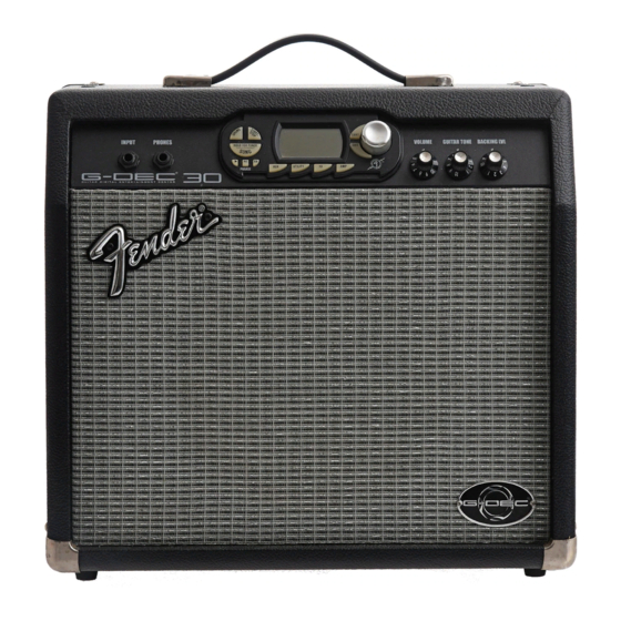
Fender G-DEC 30 Service Manual
Hide thumbs
Also See for G-DEC 30:
- Owner's manual (128 pages) ,
- Diagram (5 pages) ,
- Midi manual (36 pages)
Advertisement
®
G-DEC
30
(This is the model name for warranty claims)
p/n 2350500000 (120V)
SERVICE MANUAL
ATTENTION:
WARRANTY SERVICE PROCEDURES
Domestic (U.S. & Canada Only): The G-Dec 30 Amplifier is not available for warranty field
service. Any Dealer/Service Center in possession of a G-Dec 30 with a warrantable defect
should contact the Fender Customer Service Support Center toll free at (866) 345-3642 or
email
service@fender.com
to arrange for a replacement. This manual should only be re-
ferred to for non-warranty repairs.
Non-Domestic: FMIC acknowledges that many of our International Distributors are able to
perform field or in-house warranty service on the G-Dec 30 Amplifier.
Fender Musical Instruments Corporation, 8860 East Chaparral Road Suite 100 Scottsdale, AZ 85250
Issued: December, 2006
Advertisement
Table of Contents

Summary of Contents for Fender G-DEC 30
- Page 1 ATTENTION: WARRANTY SERVICE PROCEDURES Domestic (U.S. & Canada Only): The G-Dec 30 Amplifier is not available for warranty field service. Any Dealer/Service Center in possession of a G-Dec 30 with a warrantable defect should contact the Fender Customer Service Support Center toll free at (866) 345-3642 or email service@fender.com...
-
Page 2: Important Notice
Fender® Musical Instruments Corporation. It is Corporation. not to be sold or assigned to another party and is disclosed solely for use by Fender Authorized • Parts marked with two asterisks ( Service Centers for purposes of product service ) indicate the and maintenance. -
Page 3: Specifications
® G-DEC (This is the model name for warranty claims) SPECIFICATIONS Model Name: G-DEC ® Release Number: PR 695 Part Numbers (120V, 60Hz) US: 2350500000 (240V, 50Hz) AUS: 2350503900 (230V, 50Hz) UK: 2350504900 (230V, 50Hz) EUR: 2350506900 (100V, 50/60Hz) JPN: 2350507900 Power Requirement: Fuses:... -
Page 4: Service Notes
® G-DEC (This is the model name for warranty claims) SERVICE NOTES nected, remove the two (2) ribbon cables from CHASSIS REMOVAL is accomplished by first the keypad PCB and LCD at P24A and P71. removing the five (5) screws from the cabinet Gently slide the PCB back enough for the jacks back panel. -
Page 5: Circuit Description
The power amplifier U10 (LM3886) is provided nega- Information is focused for its effective use while tive current feedback from sense resistor R119 maintaining the security of Fender® proprietary in- through C92 and R112. DC feedback is provided by formation wherever possible. -
Page 6: Power Supplies
® G-DEC (This is the model name for warranty claims) DSP PCB POWER SUPPLIES The DSP PCB is connected to the main PCB via 30 The power transformer (PT) secondaries are con- pin header U24 for all power supply, master clock nected to the main PCB at connector P5. -
Page 7: Midi Interface
Updater utility available from www.fender.com. USER INTERFACE Button operation is created by contacts on the back- side of the elastomeric keypad shorting to adjacent pads on the keypad PCB when pressed. The Data Wheel (16 position rotary encoder S2) pro- duces 4 bits of data that is processed directly by the uPC. - Page 8 + * Access to this part or assembly is controlled. Please contact the FMIC Customer Service Department. ** Safety Requirement part. Replacement must match Safety Agency…–Value, if specified –Type, if specified –Approval Mark(s) if on part. shaded + ** Both a unique Fender® part and a Safety Requirement part as defined above.
-
Page 9: Parts List
+ * Access to this part or assembly is controlled. Please contact the FMIC Customer Service Department. ** Safety Requirement part. Replacement must match Safety Agency…–Value, if specified –Type, if specified –Approval Mark(s) if on part. shaded + ** Both a unique Fender® part and a Safety Requirement part as defined above. -
Page 10: End Item Assembly
+ * Access to this part or assembly is controlled. Please contact the FMIC Customer Service Department. ** Safety Requirement part. Replacement must match Safety Agency…–Value, if specified –Type, if specified –Approval Mark(s) if on part. shaded + ** Both a unique Fender® part and a Safety Requirement part as defined above. - Page 11 ® G-DEC (This is the model name for warranty claims) Service Diagram List Service Diagram (Schematic) ....DEC 30 MAIN PCB Service Diagram (PCB Assembly) ....DEC 30 MAIN PCB Service Diagram (Schematic) ....DEC 30 DSP PCB Service Diagram (PCB Assembly) ....DEC 30 DSP PCB...


Need help?
Do you have a question about the G-DEC 30 and is the answer not in the manual?
Questions and answers