
Related Manuals for Elektor 19883

Summary of Contents for Elektor 19883
- Page 1 V3.2 Step-by-step instructions from First Start-up to Final Adjustments 2 MHz LCR Meter Kit Assembly & Calibration Jean-Jacques Aubry ● 1...
- Page 2 2 MHz LCR Meter Kit AU2019 Assembly Manual ● 2...
- Page 3 Note: Small differences may exist between the kit as received compared to the version pictured. These differences are inconsequential.
-
Page 4: Main Technical Specifications
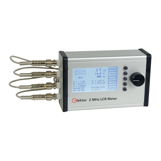
2 MHz LCR Meter Kit AU2019 Assembly Manual Main Technical Specifications - Parameter values (principal and secondary) Display - Equivalent circuit: series or parallel - Frequency - |Z| - Φ - Q or D - Voltage and current of DUT (Vx and Ix) - Test voltage (AC) and polarisation (DC) - Range hold status (R_Hold) - Labels for multi-function buttons (right-hand side) -
Page 5: Table Of Contents
Table of content Main Technical specifications ......4 2 • Let’s mount the four BNC sockets ......3 •... - Page 6 2 MHz LCR Meter Kit AU2019 Assembly Manual 1 • Contents of your Kit Check that the kit as received is complete. It must include: 3. Assembled MCU board (BNC connectors not mounted). 4. Assembled Display board (without the button of the rotary switch). Note: the LCD has a protective film so transparent that it can go unnoticed.
- Page 7 1 • Contents of your Kit 6. Flatcable (reversible). 7. Button, Ø 24mm. 8. USB cable (mini-USB / USB A). 9. Test clip with two Kelvin clips and 4 BNC connectors. ● 7...
- Page 8 2 MHz LCR Meter Kit AU2019 Assembly Manual 10. Four jumpers for settings during calibrations. 11. Screwdriver (trimming tool). Hammond case. - machined body - machined and screen-printed front panel - machined and screen-printed BNC side - machined and screen-printed USB side - 2 black plastic frames [+ special screws (8) and rubber feet (4)] 12a.
-
Page 9: Let's Mount The Four Bnc Sockets
2 • Let’s mount the four BNC sockets Screws and bolts. - 5 x M3 male-female standoffs, 6 mm high - 5 x 4 mm Pozidrive countersunk M3 screws - 1 flat washer DM3, thickness 0.5 mm - 5 x M3 self-locking nuts 13. - Page 10 2 MHz LCR Meter Kit AU2019 Assembly Manual Position the front panel on this board and secure it with 4 x 4 mm countersunk screws, then tighten the nuts. 4 mm Front Panel 6 mm standoff MF Display PCB M3 (Prevailing Torque Type Hex Thin Nut) 14a.
-
Page 11: My First Start-Up
4 • My first start-up 15. Partially assembled LCR-meter during the settings. (Photo:Jean-Jacques Aubry) Both the front panel and the MCU board can be slid out of the case, giving access to all the adjustment points without the risk of accidental electrical contact between the two boards! If the MCU board does not slide smoothly, it may be necessary to slightly file the edges of the PCB... - Page 12 2 MHz LCR Meter Kit AU2019 Assembly Manual (All screendumps by Jean-Jacques Aubry) 16 a-b-c-d. Different displays during the start-up of the assembled LCR Meter. The five pushbuttons (to the right of the display) in conjunction with the rotary knob (which is also a pushbutton) allow a dialogue between the user and the device.
-
Page 13: Calibration Menu
5 • Calibration menu Confirm your choice by pressing the [OK] button. Press the [EXIT] button to leave all settings unchanged. Choose your language (English, German, French, Dutch) in the corre- sponding menu. • to the calibration menus by a long press (the display responds to the long press by flashing briefly). - Page 14 2 MHz LCR Meter Kit AU2019 Assembly Manual Do not connect anything to the BNC sockets! R_Hold must be OFF 5.1 Sinewave generator offset adjustment Using your multimeter, measure the DC voltage at TP7 (this is the out- put of U26C). Using R146, adjust it as close as possible to 0 V. Press [OK] to exit the menu.
- Page 15 5 • Calibration menu 17. Location of the components mentioned in the instructions for calibration. (Photo by Jean-Jacques Aubry) ● 15...
- Page 16 2 MHz LCR Meter Kit AU2019 Assembly Manual The device has 54 predefined measurement frequencies: At each step of the calibration, the parameters of the measurement chain in the instrument are calculated for each of the above frequen- cies. This will take a few minutes each time! At the end of each of the following steps you will be asked to confirm to save the new values.
- Page 17 5 • Calibration menu 5.5 PGA2: Calibration at gain 10 Insert a jumper on J8, J9 and J11. First, set C51 to have ⏐Phi⏐< 0.3 and, if good, press the [OK] button that will appear. If not, exit by pressing [EXIT] and correct the problem! The gain and phase for the PGA2 (with a gain of 10) will then be calcu- lated at each of the predefined frequencies.
-
Page 18: Final Mounting In The Hammond Case
2 MHz LCR Meter Kit AU2019 Assembly Manual Note: As long as all calibrations are not carried out at least once, no cor- rection is made to the measured value. That's why "open-circuit" and "short-circuit" calibration should be completed without the Kelvin ca- bles. -
Page 19: Final Adjustments
7 • Final adjustments Important: Do not use nuts to secure the BNC sockets to the side panel of the enclosure. Finish the assembly by installing the four rubber feet. 7 • Final adjustments Connect the Kelvin cables to the BNC connectors. Repeat the Trim procedures (§5.10 and §5.11) to compensate for the new, interfering components. - Page 20 2 MHz LCR Meter Kit AU2019 Assembly Manual knob changes the value. After validation, this value is used. It is dis- played in negative and can no longer be changed by the rotary knob. A further long press on the rotary knob is required to exit this mode. The saved value will be proposed at the next request.
- Page 21 8 • Stand-alone mode A long press on this button enables/disables the display of the measurement chain parameters: Range from 1 to 4, PGA gain in voltage measurement (1 or 3 or 10), PGA gain in current measurement (1 or 3 or 10). 21.
- Page 22 2 MHz LCR Meter Kit AU2019 Assembly Manual The second step allows you to select the standardized value in this series. 8.1.4 Sorting This menu starts the comparison, displaying the measured value (top), the upper and lower limits, and of course the success (PASS) or failure (FAIL) of the comparison.
- Page 23 8 • Stand-alone mode 8.2.2 Checking the languages loaded in high memory If there are no languages loaded, the following messages are dis- played: No Language loaded. Restart in PC Mode. Use the AU2019 prog. to load them See § 9.2.5 to load the language file. 8.2.3 Checking supply voltages If a fault is detected during the power supply check, the message “PS Test Error, code X “...
-
Page 24: Use In Pc Mode
2 MHz LCR Meter Kit AU2019 Assembly Manual 9 • Use in PC mode Start the device in PC mode (the message Waiting for the GUI... is dis- played) and, a few seconds later, run the AU2019 program on the PC. 22. - Page 25 9 • Use in PC mode 9.1 Port menu From this menu, you can close an already open port and then choose a new port. 9.2 Settings menu 9.2.1 Sort If the sorting parameters have already been defined, a floating window opens and displays the same information as in Stand-alone mode.
- Page 26 2 MHz LCR Meter Kit AU2019 Assembly Manual 9.3 AU2019 menu 9.3.1 About AU2019 This window provides information about the Bootloader, Firmware and AU2019 program versions. 9.3.2 Qt-About This window provides information about the version of Qt used by the AU2019 program.
-
Page 27: Updates
10 Updates IMPORTANT! 10 Updates IMPORTANT! It is highly recommended to check the project page of the LCR meter on the the ElektorLabs website where the most recent software can be downloaded ("Updates from the Author"): www.elektormagazine.com/labs/remake-lcr-meter The update operation is described in the Operating Instructions: LCR Meter AU2019 - EN Operating Instructions (§4.2.4 and §4.2.5). -
Page 28: Other Information Sources
Various information documents (Operation, Operating instructions, PC interface, etc...) in English and French can be downloaded from this page: www.elektormagazine.com/magazine/elektor-167/59255 The file named 190311 AU2019 DOC EN & FR 2021-01-04.zip on the “Software” tab contains useful information. • LCR Meter AU2019 - EN Operation Rev 6b.pdf Description of the device’s operation. - Page 29 Other information sources • LCR Meter AU2019 - EN The text file Rev 4a.pdf To change the displayed texts or add a language. Description of the formatting of this file. • Creating an AU2019 Android application_b.pdf • AU2019 - Building Android application with Cordova_b.pdf These two files explain how to create / modify the AU2019 application for an Android smartphone/tablet.
-
Page 30: Appendix (Lcr6 Texts V3.Txt)
2 MHz LCR Meter Kit AU2019 Assembly Manual Appendix (LCR6 texts v3.txt) Messages displayed by the LCR meter in English, French, German or Dutch depending on the user’s choice. // ******************************** Calibratie bereik 4 :04 13 LANG_ARRAY Afregeling alle freqs <kortsl.> // -------------------------------- Afregeling alle freqs <open>... - Page 31 Appendix (LCR6 texts v3.txt) Sauvegarder le gain? Ausführung Kalibrierung Bereich 4 Sélectionner la valeur normalisée Fehler, Abbruch -> Régler R146 pour 0V en TP7 Ausführung Kalibrierung PGA2 Gain3 Sauvegarde des données du Trim... Ausführung Kalibrierung PGA2 Gain10 Pas de données Trim à sauvegarder Kurzschluss-Abgleich, bitte warten Sauvegarder les valeurs? Leerlauf-Abgleich, bitte warten...
- Page 32 2 MHz LCR Meter Kit AU2019 Assembly Manual DC Bias-stroom: 0 tot 50mA AC niveau: 0.1V RMS tot 1V RMS Gemeten spanning op TP6 // ******************************** :07 36 MENU_ARRAY // English ------------------------ Language Q limit for secondary display Sorting parameters Sort AC level DC bias...
- Page 33 Appendix (LCR6 texts v3.txt) ● 33...
- Page 34 Calibration of the range 1 • Calibration of the range 2 • Calibration of the range 3 • Calibration of the range 4 • <Short-circuit> Trim, all freq. • <Open-circuit> Trim, all freq. Elektor International Media BV www.elektor.com ● 34...
Need help?
Do you have a question about the 19883 and is the answer not in the manual?
Questions and answers