Table of Contents
Advertisement
Quick Links
INSTALLATION/OPERATION/MAINTENANCE FOR
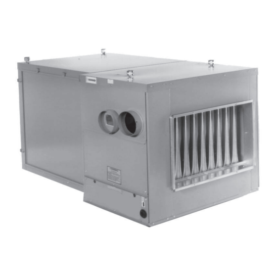
SEPARATED-COMBUSTION PACKAGED FURNACE/BLOWER
• Failure to follow safety warnings exactly could result in serious injury, death, or property
damage.
• Improper installation, adjustment, alteration, service, or maintenance can cause serious injury,
death, or property damage.
• Installation and service must be performed by a qualified installer, service agency, or the gas
supplier.
• Be sure to read and understand the installation, operation, and service instructions in this
manual.
• Do not store or use gasoline or other flammable vapors and liquids in the vicinity of this or
any other appliance.
• Do not try to light any appliance.
• Do not touch any electrical switch; do not use any phone in your building.
• Leave the building immediately.
• Immediately call your gas supplier from a phone remote from the building. Follow the gas
supplier's instructions.
• If you cannot reach your gas supplier, call the fire department.
DO NOT DESTROY. PLEASE READ CAREFULLY. KEEP IN A SAFE PLACE FOR FUTURE REFERENCE.
MODEL SCE
⚠ DANGER ⚠
FIRE OR EXPLOSION HAZARD
WHAT TO DO IF YOU SMELL GAS
Revision: SCE-IOM (01-22) 207697-B
Supersedes: I-SCE (04-21) 207697-A
Advertisement
Table of Contents

Related Manuals for Reznor SCE


Summary of Contents for Reznor SCE
- Page 1 Revision: SCE-IOM (01-22) 207697-B Supersedes: I-SCE (04-21) 207697-A INSTALLATION/OPERATION/MAINTENANCE FOR SEPARATED-COMBUSTION PACKAGED FURNACE/BLOWER MODEL SCE ⚠ DANGER ⚠ FIRE OR EXPLOSION HAZARD • Failure to follow safety warnings exactly could result in serious injury, death, or property damage. • Improper installation, adjustment, alteration, service, or maintenance can cause serious injury, death, or property damage.
-
Page 2: Table Of Contents
Electronic Modulation Between 20–28% and 100% Firing Rate (Option AG40) . . . . . . . . . . . . . . . . . . . . . . . . . . . . . . . . 35 SCE-IOM (01-22) 207697-B... -
Page 3: General Information
• This unit has been design-certified by the Canadian Standards Association to ANSI Standards and is available for use with either natural or propane gas . The type of gas, the rate, and the electrical characteristics are on the unit rating plate . SCE-IOM (01-22) 207697-B... -
Page 4: References
• Installation should be done by a qualified agency in accordance with the instructions in this manual and in compliance with all codes and requirements of authorities having jurisdiction. • The instructions in this manual apply only to the model SCE blower-type unit heater with blower cabinet. -
Page 5: Separated Combustion
. Wiring is not in accordance with the diagram furnished with the heater . c . Unit is installed without proper clearance to combustible materials . Dimensions All dimensions for the model SCE unit heater are shown in Figure 1 and are listed in... - Page 6 GENERAL INFORMATION—CONTINUED STANDARD MODEL SCE MODEL SCE WITH OPTIONAL HORIZONTAL INLET WITH DUCT FLANGES Figure 1. Model SCE Dimensions in Inches (±1/8 (mm ±3)) Table 2. Dimensions Unit Size Dimension 150, 175 200, 225 (See Figure Inches ±1/8 (mm ±3)
-
Page 7: Weights
15–20 feet (4 .5–6 meters) . Hazards of Chlorine ⚠ WARNING ⚠ SC series separated-combustion units are not designed or approved for use in atmospheres containing flammable vapors or atmospheres highly-laden with chlorinated vapors. SCE-IOM (01-22) 207697-B... -
Page 8: Installation
. Also, if your unit is equipped with any of the gas control options listed in Table 5, ensure that these parts are available at the job site . SCE-IOM (01-22) 207697-B... -
Page 9: Suspension
Figure Figure 2. Suspension Methods Mounting NOTE: Support is required where furnace and blower cabinets meet. • Model SCE requires six mounting support locations—three on each side—as shown in Figure Figure 3. Support Locations SCE-IOM (01-22) 207697-B... -
Page 10: Duct Connections
. Table 6. Duct Connection Dimensions Unit Size 150, 175 200, 225 250, 300 Dimension G (Inches (mm) 15-1/4 (387) 20-3/4 (527) 26-1/4 (667) 34-1/2 (876) 40 (1016) 45-1/2 (1156) *See Figure Figure 5. Duct Connection Dimensions SCE-IOM (01-22) 207697-B... -
Page 11: Requirements And Suggestions For Connecting And Installing Ducts
• Return air duct/furnace connection: All return air ducts should be attached and sealed to the return air flanges to provide airtight connections . • Return air duct/grill size: Ensure that return air ducting or grills have a free area equal to the size of the return duct connection . SCE-IOM (01-22) 207697-B... -
Page 12: Venting/Combustion Air Connections
• These instructions apply to installation and use of the concentric adapter and vent/combustion air kit (option CC2 or CC6) designed for use with all Reznor separated-combustion products . The systems illustrated in this manual are the only venting/combustion air systems approved for these separated-combustion units . Do not use this concentric adapter box with any other products . -
Page 13: Specific Venting Requirements: Venter Outlet And Combustion Air Inlet Connections
All separated-combustion units MUST BE equipped with both combustion air and exhaust piping to the outdoors. Model SCE heaters have both an inlet air and a venter outlet connection . Both are 6 inches (152 mm) in diameter for all unit sizes . -
Page 14: Specific Venting Requirements: Support
. Do not rely on the heater or the adapter box for support of either horizontal or vertical pipes . Use noncombustible supports on vent pipe . NOTE: The double-wall vent terminal pipe does not attach to the concentric adapter box and must be supported during installation. SCE-IOM (01-22) 207697-B... -
Page 15: Specific Venting Requirements: Clearance
When pipe diameters differ, depending on direction of airflow, join the pipes with either a tapered reducer or enlarger as shown in Figure 10 . SCE-IOM (01-22) 207697-B... -
Page 16: Vent Terminal Options
UNIT SIZES 200–400 WITH 7-INCH PIPE BETWEEN FURNACE AND BOX Figure 10. Concentric Adapter Box Connections Vent Terminal Options Figure 11 . Vent terminal options CC2 (vertical vent configuration) and CC6 (horizontal vent configuration) are shown in SCE-IOM (01-22) 207697-B... -
Page 17: Vertical Vent Terminal (Option Cc2) Installation
Figure 110052 Exhaust vent terminal assembly (see 53330 Combustion air inlet assembly (see Figure 207232 Concentric adapter box bracket 53335 High-temperature silicone sealant, tube EXHAUST VENT TERMINAL ASSEMBLY COMBUSTION AIR INLET ASSEMBLY Figure 12. Option CC2 Components SCE-IOM (01-22) 207697-B... - Page 18 . Ensure that hole accommodates 8-inch (203-mm) combustion air pipe . Thimble may be required depending on wall construction and/or local codes . Larger diameter combustion air pipe serves as clearance for vent pipe on non-combustible construction . SCE-IOM (01-22) 207697-B...
- Page 19 14) to concentric adapter box. NOTE: The longer angle of the concentric adapter box bracket has five 7/32-inch holes that allow the position of the bracket on the box to be adjusted. Figure 14. Concentric Adapter Box Brackets SCE-IOM (01-22) 207697-B...
- Page 20 . Position concentric adapter box to match pipe runs and secure short angles of concentric adapter brackets Figure 14) to underside of roof using field-supplied hardware . (see c . Install field-supplied flashing around combustion air pipe on roof outside . SCE-IOM (01-22) 207697-B...
- Page 21 10 . using 7-inch piping (unit sizes 200–400), install tapered enlarger as shown in b . Seal pipe joints with tape or sealant . 11. Verify compliance with Figure 13 and with all specific venting requirements listed above. SCE-IOM (01-22) 207697-B...
-
Page 22: Horizontal Vent Terminal (Option Cc6) Installation
205883 Kit package 205885 Concentric adapter box (see Figure 53316 Assembly, screened exhaust (see Figure Figure 205894 Inlet guard (see 37661 Screw, sheet metal, #10-16 × 1/2 207232 Concentric adapter box bracket 53335 High-temperature silicone sealant, tube SCE-IOM (01-22) 207697-B... - Page 23 If discoloration is an esthetic problem relocate the vent or install a vertical vent. e . Refer to Table 11 to ensure that location complies with minimum clearance requirements . SCE-IOM (01-22) 207697-B...
- Page 24 . Insert combustion air pipe out through wall . Figure 14) of concentric adapter box brackets to wall . b . Secure short angles (see c . Seal or flash inlet air pipe on outside using sealant and/or field-supplied flashing . SCE-IOM (01-22) 207697-B...
- Page 25 NOTE: If vent pipe is inserted from outside, the exhaust cap may be attached before the double-wall vent pipe is installed. If cap is attached first, ensure that the baffle strips are positioned correctly when attaching the vent terminal pipe to the vent run (refer to step 8d below). SCE-IOM (01-22) 207697-B...
-
Page 26: Piping Connections
• Test pressures above 1/2 psi—disconnect the heater and manual valve from the gas supply line to be tested. Cap or plug the supply line. • Test pressures below 1/2 psi—before testing, close the manual valve on the heater. SCE-IOM (01-22) 207697-B... -
Page 27: Gas Supply Piping
• After all connections are made, disconnect the pilot supply at the control valve and bleed the system of all air . Reconnect the pilot line and leak test all connections by brushing on a soap solution . SCE-IOM (01-22) 207697-B... -
Page 28: Condensate Drain Installation
NOTE: The above are not supply line sizes . They are gas connection sizes for a standard unit . Condensate Drain Installation Model SCE furnaces are certified for installation upstream or downstream from a cooling coil . When installed downstream from a refrigeration system, condensation will form and, therefore, adequate provision must be made to dispose of condensate . -
Page 29: Electrical Connections
1 .25 × maximum total input amps . Control Wiring • The heater is equipped with a low-voltage (24V) control circuit . Refer to Table 15 for field-supplied control wiring sizes . SCE-IOM (01-22) 207697-B... -
Page 30: Controls
. The main burners will remain off until the system has cooled and/or the flue system resistance is reduced . Table 17 Refer to for approximate water column negative pressure readings and combustion air proving switch setpoints for sea level operating conditions . SCE-IOM (01-22) 207697-B... -
Page 31: Blower Fan Control
60 Hertz (Hz) is maximum speed . Speed must be within the temperature rise range of a model SCE series 6 heater: 30–90°F . • Follow the variable frequency controller manufacturer’s instructions that are packaged with the heater (in the owner’s envelope) to program the variable frequency drive settings . -
Page 32: Optional Two-Stage Control (Heating Only Application)
3°F . Due to different cfm settings and outside air temperatures, the average downstream outlet temperature may not match the ductstat setting exactly . After the installation is complete, adjust the setpoint of the ductstat to achieve the desired average outlet air temperature . SCE-IOM (01-22) 207697-B... -
Page 33: Optional Ductstat With Electronic Remote Setpoint Module (Option Ag15 Or Ag16)
(55–90°F) is identified as option AG8 or AG9 . The temperature selector setting for option AG8 is on the amplifier (see Figure 25) . Option AG9 has a remote temperature selector . Both systems are available with an override thermostat . SCE-IOM (01-22) 207697-B... -
Page 34: Computer-Controlled Electronic Modulation Between 50% And 100% Firing Rate (Option Ag21)
. Control of the system Figure 25) with a corresponding remote temperature dial . is through a Maxitrol amplifier (see Note: Arrangement may vary slightly depending on gas valve; components are the same. Figure 26. Option AG39 Manifold Arrangement SCE-IOM (01-22) 207697-B... -
Page 35: Electronic Modulation Between 20-28% And 100% Firing Rate (Option Ag40)
3 .7 5 .0 40 .3–175 3 .7 5 .0 51 .8–200 3 .9 5 .0 51 .8–225 3 .9 5 .0 69–250 4 .0 5 .0 69–300 4 .0 5 .0 100–400 4 .4 6 .0 SCE-IOM (01-22) 207697-B... - Page 36 Terminal 84 and switch. switch. Terminal 7? Terminal 2? Replace the Replace ignition primary manifold permissive pressure switch. relay. Figure 27. Troubleshooting Guide for Checking Bypass Combustion Air Damper Safety Circuit on Units with Option AG39 or AG40 SCE-IOM (01-22) 207697-B...
-
Page 37: Pilot And Ignition Systems
1 .45 mm 9791 • Burner Carryover Systems: All natural gas burners, except when equipped with electronic modulation option AG39 or AG40, are equipped with two flash carryover systems—one on each end of the burner rack . SCE-IOM (01-22) 207697-B... -
Page 38: Dampers And Damper Controls
. (1) Outside Air Damper (5) Potentiometer (2) Return Air Damper (6) Mixed Air Controller (3) Damper Motor (7) Warmup Control (4) Potentiometer (8) Remote Potentiometer Figure 29. Typical Damper Controls SCE-IOM (01-22) 207697-B... -
Page 39: Dirty Filter Switch
Checking and Adjusting Belt Tension section) Reversing Blower Rotation ‰ Check blower rotation (refer to section) ‰ Verify removal of all shipping supports (refer to Uncrating/Unpacking section) Damper Linkage Adjustment ‰ Check damper linkage (refer to section) SCE-IOM (01-22) 207697-B... -
Page 40: Startup
‰ If system is equipped with optional dirty filter switch, refer to section for instructions to set switch . ‰ Place owner’s envelope containing Limited Warranty Card, this manual, and any optional information in accessible location near heater . Follow instructions on envelope . SCE-IOM (01-22) 207697-B... -
Page 41: Adjustments
. If ductwork is added to an installation, it may be necessary to increase the blower speed . Decreasing blower speed increases outlet temperature . Increasing blower speed decreases outlet temperature . SCE-IOM (01-22) 207697-B... -
Page 42: Reversing Blower Rotation
8 .40 13 .20 460V/3PH 0 .75 0 .80 1 .00 1 .30 1 .60 2 .60 3 .30 4 .20 6 .60 575V/3PH — — — — 1 .30 2 .10 2 .60 3 .40 5 .30 SCE-IOM (01-22) 207697-B... -
Page 43: Measure And Adjust Manifold (Outlet) Gas Pressure
3 . Normally, adjustments to the factory-preset regulator should not be necessary . If adjustment is necessary, set pressure to correct settings by turning the regulator screw IN (clockwise) to increase pressure or OUT (counterclockwise) to decrease pressure . Consult the valve manufacturer’s literature provided with the furnace for more detailed information . SCE-IOM (01-22) 207697-B... -
Page 44: High Elevation (>2,000 Feet/609 Meters) Installations
5 . Check all connections for gas leaks using commercial leak-detecting fluid or rich soap and water solution . Leaks are indicated by presence of bubbles . If leak is detected, tighten connection . If leak cannot be stopped by tightening connection, replace part(s) . SCE-IOM (01-22) 207697-B... -
Page 45: Conversion To Lp (Propane)
If LP (propane) conversion is required, convert the unit in accordance with form OPT-GC listed in Table 1 . When conversion is complete, verify that the input rate is correct . SCE-IOM (01-22) 207697-B... -
Page 46: Burner Air Shutter Adjustment
1 . Loosen setscrew on return air damper rod at damper arm . 2 . Manually open return air dampers . While dampers are opening, damper rod and arm will automatically move to their correct positions . 3 . Tighten setscrew . SCE-IOM (01-22) 207697-B... -
Page 47: Dirty Filter Switch Adjustment
WHILE UNIT IS OPERATING NEGATIVE PRESSURE CONNECTION ON FRONT OR TOP OF SWITCH SENSES BLOWER SIDE OF FILTERS POSITIVE PRESSURE CONNECTION ON BACK OR BOTTOM OF SWITCH SENSES AIR INLET SIDE OF FILTERS Figure 33. Dirty Filter Switch SCE-IOM (01-22) 207697-B... -
Page 48: Maintenance
LOW FIRE PRESSURE TAP HIGH FIRE REGULATOR REGULATOR REGULATOR ADJUSTING ADJUSTING SCREW ADJUSTING SCREW SCREW 1/8-INCH INLET PRESSURE TAP 1/8-INCH OUTLET 1/8-INCH INLET PRESSURE TAP PRESSURE TAP SINGLE-STAGE VALVE TWO-STAGE VALVE Figure 34. Combination Gas Valve Test Connections SCE-IOM (01-22) 207697-B... -
Page 49: Vent/Combustion Air System Maintenance
. Pull main burners horizontally away from injection opening and lift out . d . Remove manifold bracket screws and remove manifold . e . Remove burner orifices . f . Remove screws and lift out pilot burner . SCE-IOM (01-22) 207697-B... -
Page 50: Cleaning Pilot And Burners
. Use a fine wire to dislodge any stubborn particles from the burner ports . 8 . Clean the burner rack carryover systems using compressed air . SCE-IOM (01-22) 207697-B... -
Page 51: Spark Ignition System Maintenance
. 3. If the above conditions are normal and main gas flow is still off, the ignition controller is probably defective. Do not attempt to service the ignition controller as it does not contain any replaceable components. SCE-IOM (01-22) 207697-B... -
Page 52: Maintenance Procedures-Continued
. TROUBLESHOOTING NOTE: If the furnace is equipped with electronic modulation option AG39 or AG40, see Figure 27 for additional troubleshooting guidelines. Refer to Table 23 to troubleshoot the unit . SCE-IOM (01-22) 207697-B... - Page 53 . Cracked ceramic at sensor Replace sensor e . Faulty ignition controller If all checks listed in Spark Ignition System Maintenance section indicate no other cause, replace ignition controller (do not attempt to repair ignition controller, which has no field-replaceable parts) SCE-IOM (01-22) 207697-B...
- Page 54 1 . Improper motor pulley adjustment Ensure that motor pulley is properly-adjusted (refer to Speed out on section) overload 2 . Improper static pressure on duct system Adjust dampers in duct system 3 . Low voltage Check power supply SCE-IOM (01-22) 207697-B...
- Page 55 NOTES SCE-IOM (01-22) 207697-B...
-
Page 56: Installation Record (To Be Completed By Installer)
For more information, contact your Factory Representative. Specifications and illustrations subject to change without notice or incurring obligations . Latest version of this manual is available at www.reznorhvac.com . ©2022 Nortek Global HVAC LLC, O’Fallon, MO . All rights reserved . SCE-IOM (01-22) 207697-B...
Need help?
Do you have a question about the SCE and is the answer not in the manual?
Questions and answers