Table of Contents
Advertisement
INSTALLATION/OPERATION/MAINTENANCE
• Failure to follow safety warnings exactly could result in serious injury, death, or
property damage.
• Be sure to read and understand the installation, operation, and service instructions
in this manual.
• Improper installation, adjustment, alteration, service, or maintenance can cause serious
injury, death, or property damage.
Do not store or use gasoline or other flammable vapors and liquids in the vicinity of
this or any other appliance.
• Do not try to light any appliance.
• Do not touch any electrical switch; do not use any phone in your building.
• Leave the building immediately.
• Immediately call your gas supplier from a phone remote from the building. Follow the
gas suppliers instructions.
• If you cannot reach your gas supplier, call the fire department.
Installation and service must be performed by a qualified installer, service agency, or
the gas supplier.
DO NOT DESTROY. PLEASE READ CAREFULLY. KEEP IN A SAFE PLACE FOR FUTURE REFERENCE.
IMPORTANT SAFETY INFORMATION . . . . . . . . . . . . . . . . . . . . . . . . . . . . . . . . . . . . . . . . . . . . . . . . . . . . . . . . . . . . . . . . . . 2
GENERAL INFORMATION . . . . . . . . . . . . . . . . . . . . . . . . . . . . . . . . . . . . . . . . . . . . . . . . . . . . . . . . . . . . . . . . . . . . . . . . . . . . 3
Installation Codes . . . . . . . . . . . . . . . . . . . . . . . . . . . . . . . . . . . . . . . . . . . . . . . . . . . . . . . . . . . . . . . . . . . . . . . . . . . . . . . . . 3
Special Installations (Aircraft Hangars/Garages) . . . . . . . . . . . . . . . . . . . . . . . . . . . . . . . . . . . . . . . . . . . . . . . . . . . . . . . . . . 3
Warranty . . . . . . . . . . . . . . . . . . . . . . . . . . . . . . . . . . . . . . . . . . . . . . . . . . . . . . . . . . . . . . . . . . . . . . . . . . . . . . . . . . . . . . . . 4
INSTALLATION . . . . . . . . . . . . . . . . . . . . . . . . . . . . . . . . . . . . . . . . . . . . . . . . . . . . . . . . . . . . . . . . . . . . . . . . . . . . . . . . . . . . . 4
Dimensions . . . . . . . . . . . . . . . . . . . . . . . . . . . . . . . . . . . . . . . . . . . . . . . . . . . . . . . . . . . . . . . . . . . . . . . . . . . . . . . . . . . . . . 4
Uncrating/Unpacking . . . . . . . . . . . . . . . . . . . . . . . . . . . . . . . . . . . . . . . . . . . . . . . . . . . . . . . . . . . . . . . . . . . . . . . . . . . . . . . 5
Clearances . . . . . . . . . . . . . . . . . . . . . . . . . . . . . . . . . . . . . . . . . . . . . . . . . . . . . . . . . . . . . . . . . . . . . . . . . . . . . . . . . . . . . . . 6
Location . . . . . . . . . . . . . . . . . . . . . . . . . . . . . . . . . . . . . . . . . . . . . . . . . . . . . . . . . . . . . . . . . . . . . . . . . . . . . . . . . . . . . . . . . 6
Weights . . . . . . . . . . . . . . . . . . . . . . . . . . . . . . . . . . . . . . . . . . . . . . . . . . . . . . . . . . . . . . . . . . . . . . . . . . . . . . . . . . . . . . . . . 6
Suspension . . . . . . . . . . . . . . . . . . . . . . . . . . . . . . . . . . . . . . . . . . . . . . . . . . . . . . . . . . . . . . . . . . . . . . . . . . . . . . . . . . . . . . 6
Mounting . . . . . . . . . . . . . . . . . . . . . . . . . . . . . . . . . . . . . . . . . . . . . . . . . . . . . . . . . . . . . . . . . . . . . . . . . . . . . . . . . . . . . . . . 7
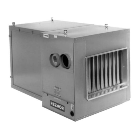
SEPARATED-COMBUSTION,
PACKAGED FURNACE/BLOWER,
MODEL SCE
⚠ WARNING ⚠
FIRE OR EXPLOSION HAZARD
WHAT TO DO IF YOU SMELL GAS
TABLE OF CONTENTS
Revision: I-SCE (09-18) PN207697R9
Supersedes: I-SCE (5-15) PN207697Rev8
Advertisement
Table of Contents

Related Manuals for Reznor SCE Series

Summary of Contents for Reznor SCE Series
-
Page 1: Table Of Contents
Revision: I-SCE (09-18) PN207697R9 Supersedes: I-SCE (5-15) PN207697Rev8 INSTALLATION/OPERATION/MAINTENANCE SEPARATED-COMBUSTION, PACKAGED FURNACE/BLOWER, MODEL SCE ⚠ WARNING ⚠ FIRE OR EXPLOSION HAZARD • Failure to follow safety warnings exactly could result in serious injury, death, or property damage. • Be sure to read and understand the installation, operation, and service instructions in this manual. -
Page 2: Important Safety Information
TABLE OF CONTENTS—CONTINUED Duct Connections . . . . . . . . . . . . . . . . . . . . . . . . . . . . . . . . . . . . . . . . . . . . . . . . . . . . . . . . . . . . . . . . . . . . . . . . . . . . . . . . . . 8 Venting and Combustion Air . -
Page 3: General Information
DANGER: A danger statement describes a potentially hazardous situation that if not avoided, will result in severe personal injury or death and/or property damage . WARNING: A warning statement describes a potentially hazardous situation that if not avoided, can result in severe personal injury and/or property damage . -
Page 4: Special Installations (Aircraft Hangars/Garages)
SPECIAL INSTALLATIONS (AIRCRAFT HANGARS/GARAGES) Installations in aircraft hangars should be in accordance with NFPA No . 409 (latest edition), Standard for Aircraft Hangars, in public garages in accordance with NFPA No . 88A (latest edition), Standard for Parking Structures, and for repair garages in accordance with NFPA No . -
Page 5: Uncrating/Unpacking
Table 1. Model SCE Dimensions Model Dimension 150 and 175 200 and 225 Code from Figure 2 Inches ±1/8 (mm ±3) 32-1/4 (819) 35-1/4 (895) 25-1/4 (641) 30-3/4 (781) 36-1/4 (921) 43-1/2 (1105) 44-1/2 (1130) 50 (1270) 55-1/2 (1410) 15-1/4 (387) 20-3/4 (527) 26-1/4 (667) 33-1/2 (851) -
Page 6: Clearances
CLEARANCES Clearance to combustibles is defined as the minimum distance—from the heater to a surface or object—that is necessary to ensure that a surface temperature of 90°F (50°C) above the surrounding ambient temperature is not Table 3 exceeded . For safety and convenience, ensure that the clearances listed in are provide as shown in the following table . -
Page 7: Mounting
Figure 3. Suspension Methods MOUNTING Model SCE requires six mounting support locations—three on each side—as shown in Figure Field-supplied supports between the blower cabinet and the furnace must extend horizontally support- ing both sections. Support Locations Figure 4. Support Locations NOTE: Support is required where furnace and blower cabinets meet. -
Page 8: Duct Connections
DUCT CONNECTIONS Refer to Figure 6 for duct connection dimensions . Size 15-1/4" (387mm) 150, 175 20-3/4" (527mm) 200, 225 26-1/4" (667mm) 250, 300 34-1/2" (876mm) 40" (1016mm) 45-1/2" (1156mm) Figure 6. Duct Connection Dimensions Requirements and Suggestions for Connecting and Installing Ducts •... -
Page 9: Venting And Combustion Air
These instructions apply to installation and use of the concentric adapter and vent/combustion air kit (option CC2 or CC6) designed for use with all Reznor separated-combustion products . The systems illustrated in this manual are the only venting/combustion air systems approved for these separated-combustion units . Do not use this concentric adapter box with any other products . - Page 10 VENTING AND COMBUSTION AIR—CONTINUED Hazards of Chlorine—Continued Remember, chlorine is heavier than air. This fact should be kept in mind when determining the installation location of heaters and building exhaust systems. The presence of chlorine vapors in the combustion air of heating equipment presents a potential corrosion hazard . Chlorine, found usually in the form of Freon or degreaser vapors, when exposed to flame will precipitate from the compound and form a solution with any condensation present in the heat exchanger or associated parts .
- Page 11 Specific Venting Requirements: Joints and Sealing Seal pipe joints as follows: • To seal joints in Category III vent pipe: follow the pipe manufacturer’s instructions for joining and sealing Category III vent pipe sections . • To seal joints in single-wall vent and combustion air pipe: secure slip-fit pipe connections using sheet metal screws or rivets .
- Page 12 VENTING AND COMBUSTION AIR—CONTINUED Specific Venting Requirements: Support Support horizontal runs every six feet (1 .8 M) . Support vertical runs of type “B” double-wall or Category III vent pipe in accordance with the requirements of the pipe manufacturer . Support single-wall vertical pipe in accordance with accepted industry practices .
- Page 13 Specific Venting Requirements: Concentric Adapter Box Pipe Connections NOTE: Do NOT make actual connections until after reading the instructions and length require- ments for installing the vent/combustion air kit. The connection requirements are the same for both vertical and horizontal systems, but the length of the double-wall pipe will vary. When pipe diameters differ, depending on direction of airflow, join the pipes with either a tapered reducer or enlarger as shown in Figure...
-
Page 14: Venting Options
VENTING OPTIONS Both venting options described below are shown in Figure 12 . HORIZONTAL VENTING VERTICAL VENTING (OPTION CC6) (OPTION CC2) Figure 12. Horizontal and Vertical Venting Options Horizontal Vent Terminal/Combustion Air Package Kit (Option CC6) Field-supplied components required for installation of the horizontal vent kit are as follows: •... - Page 15 c . Allow downward pitch of 1/4-inch per foot (6 mm per 305 mm) for condensate drain . NOTE: Local codes supersede all provisions in these instructions and in National Fuel Gas Code Z223.1. d . Ensure that distance of vent terminal from adjacent public walkways and buildings and window and building openings complies with local codes .
- Page 16 VENTING OPTIONS—CONTINUED Option CC6 Installation Instructions—Continued 4. Connect concentric adapter box: a . Refer to Figure 14 to attach brackets to box . b . Connect outside portion of combustion air pipe to box . Determine length by measuring bracket length from box to wall plus wall thickness and plus 2 inches (51 mm) .
- Page 17 g . Install indoor combustion air pipe . If using 6-inch piping, secure single-wall combustion air pipe run to collar on concentric adapter box using sheet metal screws . If using 7-inch piping (sizes 200–400), install tapered Figure 11 . enlarger as shown in h .
-
Page 18: Vertical Vent Terminal/Combustion Air Package Kit (Option Cc2)
VENTING OPTIONS—CONTINUED Vertical Vent Terminal/Combustion Air Package Kit (Option CC2) Field-supplied components required for installation of the horizontal vent kit are as follows: • Vent and combustion air piping (refer to Table • Tapered vent pipe diameter reducers and/or increasers, as required •... - Page 19 REAR SIDE VIEW VIEW Figure 17. Option CC2 Installation 2. Install vent pipe and combustion air pipe runs: Specific Venting Requirements: a . Connect piping to heater in accordance with specifications listed above in Piping Specific Venting Requirements: Venter Outlet and Combustion Air Inlet Connections .
- Page 20 VENTING OPTIONS—CONTINUED Option CC2 Installation Instructions—Continued DETAIL A Figure 18. Vertical Vent Piping Installation e . Refer to Figure 14 to attach concentric adapter box brackets to wall f . Flash combustion air pipe on outside . Flashing is field-supplied . 5.
-
Page 21: Gas Piping And Pressures
b . Ensure that double-wall terminal vent pipe is in proper direction and slide end of pipe into box and out through combustion air pipe . Position vent pipe to lengths determined above . NOTE: The double-wall vent pipe does not attach to the box. The installer must provide support. Figure 9) . - Page 22 GAS PIPING AND PRESSURES—CONTINUED Pressure Testing Gas Supply Piping—Continued • All piping must be in accordance with requirements outlined in the National Fuel Gas Code ANSI/Z223 .1 (latest Installation Codes) . Gas supply piping installation should conform edition) or CSA B149 .1 and B149 .2 (refer to with good practice and with local codes .
- Page 23 • After all connections are made, disconnect the pilot supply at the control valve and bleed the system of all air . Reconnect the pilot line and leak test all connections by brushing on a soap solution . Sizing Gas Supply Lines NOTE: When sizing supply lines, consider the possibility of future expansion and increased requirements.
-
Page 24: Electrical Supply And Connections
GAS PIPING AND PRESSURES—CONTINUED Instructions to Check Valve Outlet (Manifold) Pressure NOTE: A manometer (fluid-filled gauge) is recommended rather than a spring-type gauge due to the difficulty of maintaining calibration of a spring-type gauge. 1 . With the manual valve (on the combination valve) positioned to prevent flow to the main burners, connect a manometer to the 1/8-inch pipe outlet pressure tap in the valve . - Page 25 A specific wiring diagram can be found in the heater junction box . Optional equipment is identified on this wiring Figure 21 Figure 22 diagram . Refer to separate instruction sheets for any optional equipment provided . See for typical wiring diagrams . Figure 21.
-
Page 26: Electrical Supply And Connections
ELECTRICAL SUPPLY AND CONNECTIONS—CONTINUED Figure 22. Typical Wiring Diagram: Model SCE with Two-Stage Gas Control I-SCE (09-18) PN207697R9... -
Page 27: Control Thermostat
CONTROL THERMOSTAT A thermostat is not supplied with the furnace . Use either an optional or a field-provided low-voltage (24V) thermostat . Install the thermostat according to the manufacturer’s instructions . A low-voltage thermostat is equipped with a heat anticipator that levels out unit cycling for optimum temperature control . -
Page 28: Limit Control
BLOWER FAN CONTROL—CONTINUED The blower fan is controlled as follows: • After the gas valve opens, there is a time delay of blower fan operation to prevent the discharge of cold air . • Blower fan operation continues after the thermostat is satisfied, as determined by the fan time delay . •... -
Page 29: Operating Valve
60 Hertz (Hz) is maximum speed . Speed must be within the temperature rise range of a Model SCE Series 6 heater: 30–90°F . Follow the variable frequency controller manufacturer’s instructions that are packaged with the heater (in the owner’s envelope) to program the variable frequency drive settings . -
Page 30: Optional Two-Stage Operation-Heating Only Application
OPTIONAL TWO-STAGE OPERATION—HEATING ONLY APPLICATION The standard combination control valve is replaced with a two-stage combination gas control valve providing for low fire or high fire operation controlled by a two-stage thermostat . The first stage (low fire) is factory-set (not field- adjustable) . -
Page 31: Optional Electronic Modulation
Optional Ductstat with Capillary Tubing (Option AG3): The unit-mounted ductstat shown in Figure 24 has an adjustable range between 0°F and 100°F with a fixed differential of 3°F . Due to different cfm settings and outside air temperatures, the average downstream outlet temperature may not match the ductstat setting exactly . After the installation is complete, adjust the setpoint of the ductstat to achieve the desired average outlet air temperature . - Page 32 OPTIONAL ELECTRONIC MODULATION—CONTINUED Electronic Modulation Between 50% and 100% Firing Rate (Option AG7, AG8, or AG9) Electronic modulation for heating that is controlled by a specially-designed room thermostat (60–85°F) is identified as option AG7 . Electronic modulation for makeup air application that is controlled by a duct sensor and temperature selector (55–90°F) is identified as option AG8 or AG9 .
- Page 33 Table 17) connects to the single-stage gas valve . To compensate The gas supply (refer to pressure requirements in for additional pressure loss through the modulating valve, the single-stage gas valve has a custom outlet pressure setting higher than when it is used on a standard gas manifold . The pilot tubing connects to the pilot port on the single-stage gas valve .
- Page 34 OPTIONAL ELECTRONIC MODULATION—CONTINUED Electronic Modulation Between 20–28% and 100% Firing Rate (Option AG39)—Continued General Instructions: For each step, Is there 24 volts Go to between Terminal 2 on #1 check to ensure that the wiring is not Troubleshooting Time Delay Relay and Chart for heater.
-
Page 35: Pilot And Ignition Systems
Computer-Controlled Electronic Modulation Between 20–28% and 100% Firing Rate (Option AG40) NOTE: Option AG40 (US Patent 6,109,255) is available only with natural gas and is not available on size 350. With option AG40, the furnace is equipped with a Maxitrol signal conditioner (see Figure 27) that receives an input signal of either 4–20 milliamps or 0–10V from a customer-supplied control device such as a computer . -
Page 36: Burner Air Shutters
BURNERS, BURNER ORIFICES, AND CARRYOVER SYSTEM—CONTINUED Table 19. Burner and Carryover Orifice Specifications Burner Orifice Carryover Orifice Model Natural Gas Propane Gas Propane Gas Drill Size Drill Size Drill Size 84437 61652 1 .45 mm 9870 11833 11830 9680 84437 61652 1 .45 mm 9680... -
Page 37: Optional Equipment
Burner Air Shutter Adjustment Screw Figure 31. Burner Air Shutter Adjustment Screw OPTIONAL EQUIPMENT OPTIONAL CONDENSATION DRAIN FOR DUCT FURNACES Model SCE furnaces are certified for installation upstream or downstream from a cooling coil . When installed downstream from a refrigeration system, condensation will form and, therefore, adequate provision must be made to dispose of condensate . -
Page 38: Optional Filter Rack And Filters
OPTIONAL DAMPERS AND CONTROLS—CONTINUED Damper Linkage -- When units are equipped with dampers, the dampers are closed during shipment. When there are both return air and outside air dampers, NOTE: The illustration is intended to show location the return damper linkage only of various air control accessories and does not must be adjusted prior to use. -
Page 39: Optional Dirty Filter Switch
OPTIONAL DIRTY FILTER SWITCH The optional dirty filter pressure switch is used to provide warning to the user by energizing an indicator light on an optional remote console . The light indicates that the filters are in need of cleaning or changing . The adjustable, single-pole/normally-open differential switch closes when an increase in pressure differential above the setpoint, is sensed across the filter bank . -
Page 40: Startup Checklist
PRE-STARTUP CHECKLIST—CONTINUED Blower Checks ‰ Check blower pulley and motor pulley to ensure that they are secure to shafts; check belt tension and alignment Belts, Blowers, and Drives) (refer to ‰ Check blower rotation (refer to Belts, Blowers, and Drives) ‰... -
Page 41: Service And Maintenance
‰ Place the Owner’s Envelope containing the Limited Warranty Card, this booklet, and any optional information in an accessible location near the heater . Follow the instructions on the envelope . ⚠ DANGER ⚠ • The gas burner in this gas-fired equipment is designed and equipped to provide safe, controlled, complete combustion. -
Page 42: Vent/Combustion Air System Maintenance
OPERATING GAS VALVE MAINTENANCE—CONTINUED " Single-S tage Outlet V alve Pressure 1/8" INLET Pressure T ap T wo-Stage V alve " Outlet 1/8" INLET Pressure Pressure T ap Figure 36. Combination Gas Valve Test Connections NOTE: A manometer (fluid-filled gauge) with an inches water column scale is recommended. a . -
Page 43: Cleaning Pilot And Burners
b . Disassemble burner rack NOTE: Natural gas burner racks manufactured before Series 6 may have a lighter tube carryover system. Break the lighter tube connection at the orifice and remove the supply tubing, the drip shield, and the lighter tube. (1) For natural gas burner rack, remove flash carryover system from manifold end of burner rack . -
Page 44: Spark Ignition System Maintenance
CLEANING PILOT AND BURNERS—CONTINUED • After the pilot is cleaned, blow away any dirt using compressed air . • Clean the main burners and burner orifices using compressed air . ⚠ CAUTION ⚠ When cleaning burner ports, do not use anything that might change the port size. •... -
Page 45: Cleaning Heat Exchanger
If the main gas valve fails to open with a normal full-size pilot flame established, check the following: a . If voltage between black and brown leads on main gas valve is 20–32 VAC and there is no main gas flow with built-in manual valve in FULL OPEN position, main valve is defective . - Page 46 TROUBLESHOOTING—CONTINUED Table 21. Troubleshooting Table —Continued SYMPTOM PROBABLE CAUSE REMEDY Pilot lights, 1 . Manual valve not open Open manual valve main valve 2 . Main valve not operating will not a . Defective valve If 24-volt power is measured at valve connections and valve remains closed, replace open valve b .
-
Page 47: Installation Record
________________________________________________________________________________________ BUILDING OWNER OR MAINTENANCE PERSONNEL: For service or repair • Contact the installer listed above. • If you need additional assistance, contact the Reznor Distributor listed above. ® • For more information, contact your Reznor Representative by calling 800-695-1901. - Page 48 Specifications and illustrations subject to change without notice or incurring obligations . ©2018 Nortek Global HVAC LLC, O’Fallon, MO . All rights reserved .
Need help?
Do you have a question about the SCE Series and is the answer not in the manual?
Questions and answers