Table of Contents
Advertisement
Quick Links
Advertisement
Table of Contents

Related Manuals for Guide Sensmart IPT Series


Summary of Contents for Guide Sensmart IPT Series
- Page 1 Instruction Manual for IPT Series Online Thermal Imager for Temperature Measuring Thanks for buying this product. Please read this manual before use and then carefully collect it for future reference. The pictures are for reference only and the products are subject to the available products.
- Page 2 InSTrucTIOnS TO uSerS SafeTy uSe PrecauTIOnS The purpose of this Manual is to ensure the users correct usage of the product to avoid danger or property damage. Please read this Instruction Manual carefully before using this product and keep it well for future reference. As shown below, the precautions are divided into “Warnings”...
- Page 3 InSTrucTIOnS TO uSerS cauTIOnS • Do not drop objects onto the device or vibrate the device vigorously, and keep the device away from locations where magnetic-field interference exists. • Please avoid the installation of the device in the vibrating surface or the place where is subject to shock.
- Page 4 DISclaIMer The user shall ensure that the Instruction Manual and this Statement of the product have been carefully read and fully understood before using this product, and the user shall install and use this product in strict accordance with this Instruction Manual of the product. The great inconvenience or even property damage and personal injury may arise in case that the user fails to install and use this product in strict accordance with this Instruction Manual.
-
Page 5: Table Of Contents
cOnTenTS chapter I list of Items ....................1 chapter II Product Overview ..................2 2.1 Product introduction ......................2 2.2 Product technical specifications ................... 2 chapter III list of Product Parts .................. 5 3.1 External view ........................... 5 3.2 Electrical interface ........................9 chapter IV Main functions .................. -
Page 6: Chapter I List Of Items
chapter I list of Items MaTerIal naMe QuanTITy Online Thermal Imager for Temperature Measuring (including lens) Power adapter (Partial selection) Power adapter plug (Partial selection) Optical disk (the content of the optical disk including SDK development kit, instruction manual of the SDK development kit interface, software and product instruction manual) Reticle(only support IPT384 and IPT640) (Partial selection) -
Page 7: Chapter Ii Product Overview
II Product Overview 2.1 Product introduction The IPT series product is the online thermal imager for temperature measuring with high performances and high accuracy. The uncooled focal plane explorer is used for stable operation and excellent performance. The product is developed based on the common interface protocol with feature-rich terminal software and the easy-to-use SDK package. - Page 8 Model IPT640 IPT384 IPT384SP-a IPT384SP-f ethernet Ethernet Control and image transmission function Ethernet type 100/1,000Mbps Video stream 1.Pure video stream,2. pure mixed stream, 3.pure temperature stream Protocol RTSP,UDP,HTTP,TCP/IP,Onvif IP allocation Static IP, dynamic IP For details, please refer to the "sdk instruction manual" in each product data download card.
- Page 9 Model IPT640 IPT384 IPT384SP-a IPT384SP-f Physical data Separate type, Separate type, front 98mm×60mm 88mm×60mm front end end 44.45mm× ×60mm ×60mm 40mm×40mm 43.85mm (with lens, (with lens, Dimensions ×41mm, ×44.53mm, excluding excluding rear end rear end external external 41mm×45mm 45mm×41mm interface) interface) ×20mm ×16.2mm...
-
Page 10: Chapter Iii List Of Product Parts
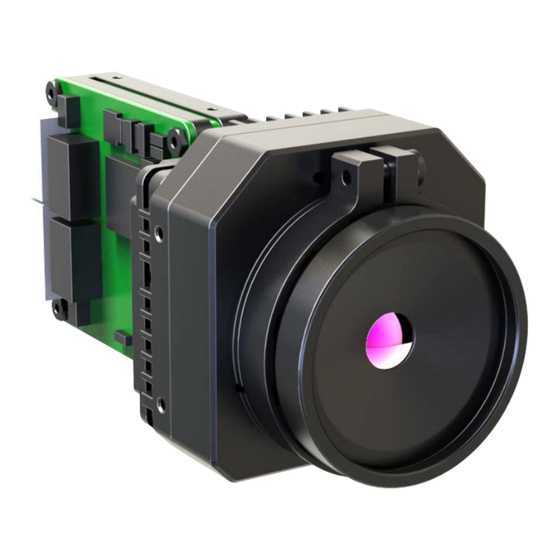
chapter III list of Product Parts 3.1 external view IPT640: fig.1 IPT640 external view fig.2 IPT640 structure and size... - Page 11 IPT384: fig.3 IPT384 external view fig.4 IPT384 structure and size note: The structural size and product appearance will vary depending on the lens.
- Page 12 IPT384SP-A: fig.5 IPT384SP-a external view fig.6 IPT384SP-a structure and size...
- Page 13 IPT384SP-F: fig.7 IPT384SP-F external view fig.8 IPT384SP-F structure and size...
-
Page 14: Electrical Interface
3.2 electrical interface Electrical interfaces in the IPT series online thermal imager for temperature measuring include interfaces such as power input interface and Ethernet interface. The electrical specifications of the interface are as follows: name of interface electrical specification It is allowed to input the DC power supply within the range of 9 - 15V and ripple wave less than 200mV, and the DC load capacity is >1A. - Page 15 Reset Button 6pin Network power input 8pin Network power output 6pin,连接可见光 8pin,连接 PC 12V-out RJ45-TX+ DGND RJ45-TX- RJ45-TX+ RJ45-RX+ RJ45-TX- RJ45-RX- RJ45-RX+ DGND RJ45-RX- DGND fig.9 Product external interface diagram...
-
Page 16: Chapter Iv Main Functions
chapter IV Main functions This chapter mainly describes the installation, preview and implementation of the specific functions of the PC software to for the purpose of normal use of the thermal imager after software installation. 4.1 Installation instruction of control software in the Pc First double-click the application installation file to install the software. - Page 17 fig. 11 Software installation interface I After clicking the “Next” button, the window for selecting the installation path and installation object will pop up. After selecting the installation path and object of the file, click the “Next” button to proceed to the next step of the installation, as shown in Fig. fig.
- Page 18 In the new pop-up window, click the “Next” button to proceed to the next step of the installation. After the installation is completed, the prompts “Installation Completed”, “Install VC2010 Runtime Library” and “Install VC2015 Runtime Library” pop up respectively. The display interfaces are as shown in Fig. 13 - Fig. 15 below: fig.
- Page 19 fig. 15 Prompt window of the installation of Vc2015 runtime library Click the “Close” button in Fig. 13 to complete the NetCoer software installation, then check the “I have read and accept the license terms” in Fig. 14 and click the “Installation” button to install the VC2010 runtime library.
-
Page 20: Operation Instruction Of Control Software In The Pc
fig. 17 Prompt window of the installation completion of Vc2015 runtime library 4.2 Operation instruction of control software in the Pc Click on the on the desktop or click on "NetCore" file in the NetCore folder in the computer “Start” to launch the NetCore software. When the software is first opened, the program interface is the device management interface of the setting interface, as shown in Fig. - Page 21 subnet mask, gateway, DNS, port back end and information about the device type, as shown in Fig. 19. fig. 19 Device management interface II of the setting interface 4.2.2 IP modification Click the “IP Settings” button shown in the Fig. 19 and the IP modification window will pop up.
- Page 22 4.2.3 Device connection Check the controls in the selected column of the child device category in the device management interface and click the “Add” button to add the device to the device list. The added device will appear in the device list. The device list shows the serial number, MAC, IP, subnet mask, gateway, DNS, port back end, device type, device name and remarks of the device, as shown in Fig.
- Page 23 Click the “Frame Rate” drop-down box and select the frame rate of the temperature data. Refer to the Fig. 22. fig. 22 Device information window The device can be removed from the device list by clicking the “Delete” button in the action bar in the device list.
- Page 24 fig. 23 Other settings interface of the setting interface Click the “Select Directory” button in the photo storage path in the other settings interface, and the window for browsing the folder will pop up. Select the corresponding folder and click “OK”.
- Page 25 4.2.5 Inquiry of software version number and SDK version number Click the “About Us” button on the setting interface, and the setting interface will switch to the “About Us” interface. In the “About Us” interface, the software version number and the SDK version number can be reviewed, as shown in Fig.
- Page 26 The display control is divided into the title bar and the display window. Title bar: Including indicator light, title, “Zoom in” or “Restore” button (when multiple devices are connected) Indicator light: indicating the current device status. “Green”: online “Gray”: offline “Red”: alarming The title is the device name and is used to distinguish the device.
- Page 27 4.2.7 The highest temperature and lowest temperature tracking of the whole picture (available under pure temperature code stream) The orange and green cursors are superimposed on the highest and lowest temperature points of the full image within the video image outputted in the display control, and the temperature value of the point is displayed.
- Page 28 4.2.9 Single-time shuttering Click the button in the main interface, the selected device will perform the single-time shuttering action. 4.2.10 Timed shutter Enter the interval time (unit: s) for each shutter action in the “Interval time” input box in the timed shutter bar of the “Setting interface of function keys”, and then click the “OK” button.
- Page 29 setting”, the timing photographing function stops. Or click the button again, the button returns to the normal state , and the timed photographing function stops. 4.2.13 Recording Select the type of the file to be stored in the “Storage type” in the recording bar of “Setting interface of function keys”.
- Page 30 4.2.15 Full screen and display multiple Click the button in the main interface, the button will light up , and the image displayed by the display control will fill the display control. Click the button in main interface, the button will light , the display image in the display control is in the center position, and the width and height of the image displayed by the display control is the width and height of the device resolution.
- Page 31 fig. 29 Device settings interface 4.2.17 Switch color band Click the “color band” button in the color band column on the device settings interface, and the image displayed by the display control will switch to the corresponding pseudo- color.
- Page 32 4.2.18 Focusing Electric focusing Click the “infrared far focus” or “infrared close focus” button on the device settings interface to drive the motor into operation and commence electric focusing. Auto focusing Click the “auto focusing” button on the device settings interface, and the image displayed by the display control will automatically adjust to a clear state.
- Page 33 fig. 30 Tool settings interface (pure video code stream mode or mixed code stream mode) In pure temperature code stream mode, click the “tool settings” button on the main interface, and the tool settings interface (pure temperature code stream mode) will pop up, as shown in Fig.
- Page 34 fig. 31 Tool settings interface (pure temperature code stream mode) 4.2.22 Character overlap In the “X” input box of the character overlap column on the tool settings interface, type in the X coordinate (relative to the image) of the character string that you wish to overlap. In the “Y”...
- Page 35 exceed the resolution width and height of the device. Click the “character overlap” button in the character overlap column on the tool settings interface, and the button will be brightened to execute the function of character overlap. According to the X and Y coordinates in the “X” and “Y” input boxes of the character overlap column on the tool settings interface, the characters in the “character string”...
- Page 36 In “Max + Min” type, cursors will be overlapped at positions with the highest temperature and the lowest temperature in the whole image, and the values of the highest temperature and the lowest temperature will be displayed at the bottom of the image. In “Max + Avg”...
- Page 37 alarm threshold in the high-temperature “alarm temperature” input box. Click OK to save the setting. In the whole-image alarm column on the tool settings interface, type in the lower limit of alarm threshold in the low-temperature “alarm temperature” input box. Click OK to save the setting.
- Page 38 Click the tool to set the interface area analysis bar button , and the line analysis object will appear in the display control, as shown in Fig. . fig. 33 line analysis object Click the tool to set the interface area analysis bar button , and a rectangular object will appear in the display control, as shown in Fig.
- Page 39 4.2.27 Temperature measurement parameters Click the “temperature measurement parameters” button on the main interface, and the temperature measurement parameters interface will pop up, as shown in Fig. 36. fig. 36 Temperature measurement parameters interface The temperature measurement parameters interface will display the device’s current temperature measurement parameters.
-
Page 40: Chapter V Troubleshooting Of Common Faults
chapter V Troubleshooting of common faults When a fault listed in the table below occurs during the working process of the thermal imager, please troubleshoot according to the recommended operation. If unable to troubleshoot, please contact the supplier or call the service hotline of our company. Fault description Presumed cause Solution...
Need help?
Do you have a question about the IPT Series and is the answer not in the manual?
Questions and answers