
Subscribe to Our Youtube Channel
Related Manuals for Advanced Radiant Systems KMI


Summary of Contents for Advanced Radiant Systems KMI
- Page 1 Installation, Operation and Service Instructions KMI RANGE HIGH EFFICIENCY HIGH INTENSITY HEATERS...
- Page 3 WARNINGS WARNING FOR YOUR SAFETY Improper installation, adjustment, alteration, service Do not store or use gasoline or other flammable or maintenance can cause property damage, injury vapors and liquids in the vicinity of this or any other or death. Read the installation, operating and appliance.
-
Page 4: Table Of Contents
CONTENTS INTRODUCTION ..........................1 Preface ................................1 The Technology ...............................1 General information ............................2 LAYOUT RECOMMENDATIONS ...................... 3 Layout Considerations .............................3 Spot Heating ..............................3 Full Building Heat ..............................4 ENGINEERING SPECIFICATIONS ....................5 Energy Supply ..............................5 CLEARANCE TO COMBUSTIBLES ....................6 INSTALLATION INSTRUCTIONS ....................6 High Intensity Mounting Instructions/Configurations ...................7 Horizontally Mounted High Intensity Heater ........................7 Angled High Intensity Heater ..............................8... -
Page 5: Introduction
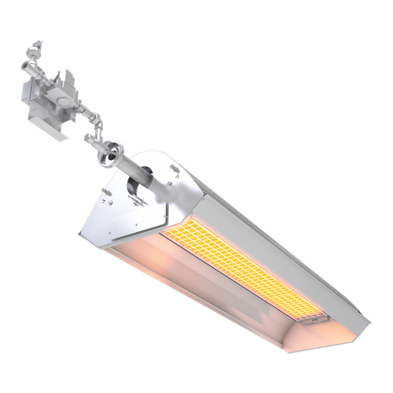
The Technology The GoGaS KMI Novus high intensity heater from the KMI series is a high-quality product with ratings from 6 kW (21,000 BTU/h) to 36 kW (125,000 BTU/h). The modern injector burner allows almost pollution-free operation, from the smallest to the largest heater unit, with only one combustion chamber. -
Page 6: General Information
INTRODUCTION This appliance must be installed in accordance with current connection and installation regulations and may only be used in adequately ventilated rooms. The installation and operating instructions must be inspected and understood before installation and before start-up. Before installation it must be checked whether local gas distributions, gas types and gas pressures as well as the settings of the appliance are compatible. -
Page 7: Layout Recommendations
LAYOUT RECOMMENDATIONS Layout Considerations • Because high intensity heaters are un-vented, verify local codes for guidance on air supply and dilution air. Also see section on Ventilation. • Check local codes for mounting requirements and the requirement for flexible gas connectors or rigid mounting. -
Page 8: Full Building Heat
ANGLE ft (m) ft (m) ft (m) 10 - 15 9 - 13 8 - 20 30 - 60 KMI-20 20,000 6 (1.9) (3 - 4.6) (2.7 - 4) (2.5 - 6.1) (9.2 - 18.3) 12 - 19 11 - 17... -
Page 9: Engineering Specifications
125,000 125,000 Single Stage SINGLE STAGE GAS PRESSURE NATURAL GAS PROPANE Minimum 6.5″ W.C. 12″ W.C. Maximum 14" W.C. 14″ W.C. Manifold 5″* W.C.* 11″ W.C. *5.25" W.C. for model KMI 90 Page 5 High Efficiency - High Intensity KMI_02142017al... -
Page 10: Clearance To Combustibles
HORIZONTALLY UP TO 30° ignited and burned. Such materials shall be considered combustible even though flame-proofed, fire-retardant KMI 20 treated or plastered. The stated clearance to combustibles KMI 40 represents a surface temperature of 90°F (50°C) above room temperature. -
Page 11: Installation Instructions
INSTALLATION INSTRUCTIONS • Figures on the below illustrate the typical mounting configurations for the Series KMI heaters; verify which is permissible by local codes. • Heaters must be hung at an angle between 0° and 30°. Typically, at the walls they are at 30° facing into the building. -
Page 12: Angled High Intensity Heater
Minimum Mounting Heights (angled at 30°) relative to Air Temperature CLEARANCES (in) RELATIVE TO AIR TEMPERATURE MODEL NO. 59° F 50° F 41° F KMI 20 162 5/8 127 9/16 115 3/8 KMI 40 152 3/4 135 7/16 KMI 60... -
Page 13: Air Plate Installation Instructions
INSTALLATION INSTRUCTIONS Air Plate Installation Instructions M5 SCREWS (QTY 4) ORIFICE HOUSING VENTURE NECK ORIFICE AIR PLATE SINGLE STAGE Single-Stage Air Plate Installation WARNING ◊ Before the orifice housing is mounted to the Venturi neck, the Air Plate and orifice sizes must be compared with the Rating plate specifications. -
Page 14: Gas Connections
INSTALLATION INSTRUCTIONS Gas Connections Connect the gas line (using an approved Flexible Gas Connector) to gas valve train assembly, see figure below for the correct and incorrect connections. INCORRECT POSITIONS CORRECT POSITIONS HEATER HEATER MOVEMENT MOVEMENT WRONG WRONG WRONG 3" MAX. DISPLACEMENT WRONG HEATER MOVEMENT... -
Page 15: Electrical Connections
INSTALLATION INSTRUCTIONS Electrical Connections WARNING ◊ For your safety, shut off the main gas valve, and disconnect all electrical supply to the High Intensity Unit. ◊ Ensure the heaters are properly grounded. ◊ Perform all work in accordance with local codes or the National Electric Code ANSI/NFPA 70 or Canadian Electrical Code CSA C22.1. - Page 16 INSTALLATION INSTRUCTIONS Electrical Connections (continued) If mechanical exhaust or humidistat is used in the building, it is typical to interconnect these in the heater circuit as shown in figure below. FAN #2 FAN #1 When using a humidistat to control exhaust HUMIDISTAT fans, wire the humidistat to cause the fan to operate on humidity rise, NOT humidity fall.
-
Page 17: Single-Stage Electrical Connection / Wiring Diagram
INSTALLATION INSTRUCTIONS Single-Stage Electrical Connection / Wiring Diagram • Connect the electrical lead wires to the gas valve control using these symbols (L1, N, and GND) and make sure to ground the valve. • Verify the input voltage going to the control assembly is a 24 V 60Hz AC before connecting to the valve. PRESSURE SWITCH OPTIONAL FIELD SUPPLIED / WIRED... -
Page 18: Ventilation
INSTALLATION INSTRUCTIONS Ventilation Buildings using high intensity radiant heaters require ventilation. High Intensity type heaters are considered un- vented gas fired appliances, requiring ventilation to supply combustion air and dilute/remove the products of combustion. Requirements for combustion air supply and dilution air vary by jurisdiction, building type and specific installation details. -
Page 19: Operation And Maintenance
OPERATION AND MAINTENANCE • Ensure the gas supply line has been purged. • Open all gas cocks to the heaters and electrically energize the system. • Follow the instructions on the heaters Lighting Instructions Label. • Check ensure that thermostat starts and shuts down the system. -
Page 20: Troubleshooting
TROUBLESHOOTING SYMPTOM POSSIBLE CAUSE CORRECTIVE ACTION Defective thermostat Heaters will not turn off Repair or replace Stuck gas valve Verify all connections Gas Odor Loose pipe connection are sealed by using an appropriate leak test Replace burner head Cracks between or across ceramic grids Burning of gas/air mixture assembly inside venturi (flashback) -
Page 21: Replacement Parts
REPLACEMENT PARTS ITEM NO. ITEM DESCRIPTION KMI MODEL NO. PART NO. P-GG030 GAS VALVE REPLACEMENT KIT 60, 90, 120 P-GG001 GAS PRESSURE SWITCH (NAT. GAS) 20, 40 P-GG002 GAS PRESSURE SWITCH (NAT. GAS) 60, 90, 120 P-GG003 GAS PRESSURE SWITCH (LP. GAS) -
Page 22: Warranty
WARRANTY The Manufacturer warrants to the original owner that the product will be free of defects in material and workmanship. For the Series KMI, the warranty for all components except for the ceramic burner head assembly is limited to 24 months from the date of installation. - Page 24 315 N Madison Street Fortville, IN 46040 317-577-0337 800-874-3285 sales@advancedradiantsystems.com www.AdvancedRadiantSystems.com KMI_02142017al...
Need help?
Do you have a question about the KMI and is the answer not in the manual?
Questions and answers