Advertisement
Quick Links
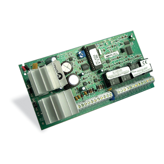
1.0 Introduction
The PC4204CX is a Power Supply/Relay Output/ Combus Repeater
Module. The PC4204CX provides a power output for system devices,
4 programmable relay outputs and an output to regenerate the
Combus data signal to allow for longer wire runs.
NOTE: Do not use any power supply other than the PC4204CX to repower
the Combus. If a power supply other than the PC4204CX is used, the
Combus repower function will not operate as intended. See the control
panel Installation Manual for details regarding this feature.
2.0 Specifications
• Transformer 16V
- 40V
AC
A
PC4204CX
• Backup battery 4Ah to 38Ah (not provided)
• Connects to control panel via 4-wire Combus
• Current draw from Combus: 30mA
• Four programmable relay contacts rated 2A, 30V
• Selectable battery charging current (800mA or 1.2A)
• AUX current: 2.2A max., with 800mA battery charge current
and 80VA transformer
• Tamper connection
3.0 Installing the PC4204CX
The PC4204CX should be located inside a compatible cabinet,
mounted in a dry, secure location.
NOTE: The PC4204CX must be installed within a fire enclosure, as
defined in EN60950. The cabinet must comply with the battery
manufacturer's installation instructions.
NOTE: The cabinet should be mounted in a safe and reliable manner. A
safety factor of 4 or higher must be provided.
Perform the following steps to mount the unit:
Please refer to the System Installation Manual for information on limitations regarding product use
and function and information on the limitations as to liability of the manufacturer.
®
Power Supply / Relay Output / Combus Repeater Module
to 80V
may be used to power the
A
DC
v 3.0 • Installation Instructions
1. 1. 1. 1. 1. Press the five plastic standoffs through the mounting holes
at the back of the cabinet.
2. 2. 2. 2. 2. Secure the cabinet to the wall in the desired location. Use
appropriate wall anchors when securing the cabinet to
drywall, plaster, concrete, brick or other surfaces.
3. 3. 3. 3. 3. Press the circuit board onto the plastic standoffs to secure
the module to the cabinet.
Once the unit is mounted, wiring may be completed.
3.3 Installation and Wiring
NOTE: The PC4204CX is intended to be PERMANENTLY CONNECTED
and should be installed by service personnel only.
Before beginning to wire the unit, ensure that all power (AC
transformer and battery) is disconnected from the control panel.
Perform the following steps to complete wiring:
1. 1. 1. 1. 1. Connect the four panel-originating Combus wires to the
PC4204CX. Connect the red, black, yellow and green
Combus wires to the RED, BLK, YEL and GRN Combus In
terminals, respectively.
If Relay 1 is being used for Combus power, connect the
Combus wires according to the diagram below. Note that
for this option, jumper Con3 must also be set for "Repower
Relay 1."
PC4204CX
Advertisement

Related Manuals for Maxsys PC4204CX


Summary of Contents for Maxsys PC4204CX
- Page 1 3. 3. 3. 3. 3. Press the circuit board onto the plastic standoffs to secure NOTE: Do not use any power supply other than the PC4204CX to repower the module to the cabinet.
- Page 2 The Combus is used by the control panel and the modules to current calculations must be made to ensure that the maximum AUX supply communicate with each other. When the PC4204CX is used to repower current is not exceeded. and extend the Combus, please refer to the wiring diagram for the Module Ratings exact wiring procedure.
- Page 3 Combus. This information can be used Maximum Length to determine which section of Combus is disabled on the system. When connecting the PC4204CX to the Combus, care must be taken 2000ft (600m) to ensure that the ‘Combus In’ terminals are connected to the...
- Page 4 Installer’s Code. Each relay output must be programmed. Please see the control panel Installation Manual and Programming Worksheets for a detailed list of output options. PC4204CX Outputs Module Number: PC4204CX # Module Number: PC4204CX # Module Number: PC4204CX # (1-16 = XX)
Need help?
Do you have a question about the PC4204CX and is the answer not in the manual?
Questions and answers