
Related Manuals for KARAM MW100K


Summary of Contents for KARAM MW100K
- Page 1 Microwave Barrier MW100K / MW200K / MW300K Installation Guide and Operating Manual...
-
Page 2: Product Inventory
Microwave barrier English version (01.12.2014) Dear Customer! Thank you for choosing our product! Before installation and use, please read this Installation Guide and Operating Manual carefully and thoroughly, so that you can take safe and full advantage of all features of the product. This manual contains information about the design, operation, application and technical parameters of the Microwave Barrier. -
Page 3: Table Of Contents
Microwave barrier Note: Power supply is not included. TABLE OF CONTENTS PRODUCT INVENTORY TABLE OF CONTENTS INTRODUCTION INTENDED USE SAFE USE MODELS PERFORMANCE CHARACTERISTICS AND FEATURES GENERAL OPERATING PRINCIPLES SELECTING THE INSTALLATION LOCATION MOUNTING THE DETECTOR INITIAL SET-UP OPERATING FREQUENCY ADJUSTMENT DETECTION SPEED ADJUSTMENT TESTING AND TUNING INSTALLING MULTIPLE DETECTORS AT ONE SITE... -
Page 4: Introduction
MODELS 328 ft. (100-meter) coverage variant MW100K MW200K 656 ft. (200-meter) coverage variant MW300K 984 ft. -
Page 5: Performance Characteristics And Features
Microwave barrier PERFORMANCE CHARACTERISTICS AND FEATURES The detector can function in areas with long grass or of uneven surfaces up to a height or height variance of 1 ft. (0.3 m) under the conditions specified below. The detector meets a climatic implementation standard of temperatures ranging from 233°K through 338°K (from -40°F through +147°F, -40°С... - Page 6 Microwave barrier the operating signal – specifically, of the frequency channel – in order to eliminate possible mutual interference of adjacent detectors. It is therefore possible to set up multiple detectors in parallel. The detector addresses a malfunction by disconnecting the outputs of the terminal control relay until the elimination of the malfunction when: a random, unanticipated chance malfunction occurs at the transmitter unit or receiver −...
-
Page 7: General Operating Principles
Microwave barrier GENERAL OPERATING PRINCIPLES The transmitter unit and receiver unit are placed at opposite ends of the area to be protected. The transmitter unit emits electromagnetic waves in the direction of the receiver unit. The receiver unit receives these waves, converts them into an electric signal, and analyzes this signal. An intruder who penetrates the detection zone –... -
Page 8: Selecting The Installation Location
Microwave barrier SELECTING THE INSTALLATION LOCATION Attention! The safety and reliability of the operation of the detector depend on the strict observation of the following requirements. The presence of water due to overflow/spillage/leakage/seepage/etc. from nearby structures (e.g., roofs, etc.) should be avoided in the direct vicinity of the detector units (in the direction of the emission, no closer than 16.40 ft. - Page 9 Microwave barrier In case of installation near power lines, the detector units should be placed no closer than 16.40 ft. (5 m) to lines of a voltage up to 35 kV, and no closer than 32.81 ft. (10 m) to lines of a higher voltage up to 500 kV.
-
Page 10: Mounting The Detector
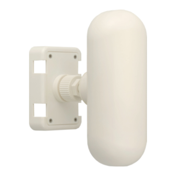
Microwave barrier MOUNTING THE DETECTOR In terms of its physical configuration, the final assembled detector is comprised of two oppositely- placed separate units – the transmitter unit and receiver unit – which are identical in size and appearance. To perform proper physical orientation of the units, it is necessary first to loosen their fixing nuts, and then to tighten them after final adjustment. - Page 11 Microwave barrier - 11 -...
-
Page 12: Initial Set-Up
Microwave barrier INITIAL SET-UP Switch on the power supply of the detector, and check its voltage at the corresponding outputs of the units. The voltage can be checked by any device that provides such measurement. The measured value, taking into account the required reserve for usage, must be between 12-36 V. After the power supply is switched on, it is necessary to perform the initial adjustment of the detector. -
Page 13: Operating Frequency Adjustment
Microwave barrier OPERATING FREQUENCY ADJUSTMENT The detector has 250 independent frequency channels (1-250) available. The difference in frequency between adjacent channels is 1 MHz. The complete range of available channels comprises 24.001-24.250 GHz. The nominal operating frequency of channel 1 is 24.001 GHz, that of channel 10 is 24.010 GHz, and that of channel 250 is 24.250 GHz. -
Page 14: Detection Speed Adjustment
Microwave barrier DETECTION SPEED ADJUSTMENT An important feature of the processing algorithm of the detector is its ability to evaluate the likely maximum speed at which an intruder could reasonably be anticipated to penetrate the detection zone in relation to the actual penetration speed of the intruder. The specification of the associated evaluation parameter is made by the user, depending on the physical characteristics of the protected area. -
Page 15: Testing And Tuning
Microwave barrier TESTING AND TUNING To implement the desired operation of the detector, it must be set to operational status after verification of the proper generation of alarm signals. It is therefore necessary to first perform test penetrations of the detection zone along its entire length, especially at particularly vulnerable points like depressions and elevations. - Page 16 Microwave barrier physical configuration of the installation so as to effectively avoid the source of such noise. Noise of an intermittent character may be caused by the sporadic penetration of the detection zone by wind-blown tree limbs; hence, the importance of strict maintenance of an adequate exclusion zone (see ‘SELECTING THE INSTALLATION LOCATION’...
-
Page 17: Installing Multiple Detectors At One Site
Microwave barrier INSTALLING MULTIPLE DETECTORS AT ONE SITE Where several detectors are installed adjacently with the intent to prevent penetration of the barrier at the so-called “blind zones” in the immediate vicinity of the detector units, a segment coverage overlap of at least 11.07 ft. (3.5 m) should be established. In such a detector configuration, detector units of the same type (transmitter unit or receiver unit) must be placed side-by-side. -
Page 18: Technical Specifications
Microwave barrier TECHNICAL SPECIFICATIONS Specification Value Detection zone length 32.81-984 ft./10-300 m Minimum required level of signal received at maximum length of the 8 dB detection zone Minimum detection zone height for a protected segment length of 8.20 ft./2.5 m 984 ft./300 m Range of detection speeds 1.64 / 6.56 / 32.81 ft./s... - Page 19 Microwave barrier Attention! The measurement (control) of the resistance of the circuits, and the isolation of the current-carrying cores of the connecting cables, can only be performed AFTER switching off the voltage of the power supply of the detector, and the disconnection of the circuits controlled. Table 2.1 –...
-
Page 20: Appendix - Software Configuration And Programming Procedures
Microwave barrier APPENDIX – SOFTWARE CONFIGURATION AND PROGRAMMING PROCEDURES For set-up and adjustment of the detector, the following additional items are necessary: ® 1 personal computer (Windows operating system) 1 USB-RS485 converter 1 mini-USB cable 1 software Installation of the USB-RS485 converter Connect the USB-RS485 converter to the computer. - Page 21 Microwave barrier Designate a destination folder for the software. click ’Next’ to continue ... Designate a destination folder in the Start Menu directory for shortcuts to the software. click ’Next’ to continue … Create a desktop icon for quick access to the software.
- Page 22 Microwave barrier Complete the installation process. click ’Finish’. Configuring the software Choose a language. click ’Next’ to continue ... Select an input function. click the ’Radar-based barrier’ check-box; click ’Next’ to continue … Specify password(s) - optional. if desired, • type password(s); •...
- Page 23 Microwave barrier Verify the settings. click ’Done’ to continue … Configuration in progress … (this may take some moments) Complete the configuration process. click ’Exit’. Connecting a transmitter or receiver to the computer Connecting a transmitter 1. Connect the green wire of the transmitter to the ’A’ socket of the USB-RS485 converter. 2.
- Page 24 Microwave barrier 2. Connect the yellow wire of the receiver to the ’B’ socket of the converter. 3. Connect the power supply of the receiver. Starting the programming procedure Click the Microwave Barrier icon. ® (in Windows 7, an error message indicating that the program is already running may appear. In this case, close the error message window and run the program as a system administrator) When the Login window appears, if a password has previously been used, type it in...
- Page 25 Microwave barrier Configuring the transmitter Complete the configuration of the transmitter first. The factory default network address of the transmitter is ’1’. Initiate communication between the device and the computer by clicking ’Start’. If successful, the default settings of the transmitter parameters are then displayed in the ’Internal state’ section of the screen accessed via the ’System’...
- Page 26 Microwave barrier network address. Programming the transmitter To program the transmitter, click the ’Transmitter’ tab at the bottom left of the ’System’ window, and then click the ’Modify’ check-box to start the programming procedure. Set the operating frequency channel of the currently addressed transmitter by specifying a value between 1 and 250 in the ’Frequency channel’...
- Page 27 Microwave barrier Configuring the receiver The factory default network address of the receiver is ’2’. Initiate communication between the device and the computer by clicking ’Start’. If successful, the default settings of the receiver parameters are then displayed in the ’Internal state’ section of the screen accessed via the ’System’...
- Page 28 Microwave barrier Programming the receiver To program the receiver, click the ’Receiver’ tab at the bottom left of the ’System’ window. Click ’Begin’, and then click the ’Modify’ check-box to start the programming procedure. First, set the operating frequency channel of the currently addressed receiver by specifying a value between 1 and 250 in the ’Frequency...
- Page 29 Microwave barrier In ’auto’ mode: In manual mode, -1 dB: In manual mode, -15 dB: - 29 -...
- Page 30 Microwave barrier The receiver also has a ’Disarmed’ check-box option (only available on devices with firmware version 3.9R or later) that permits the temporary disabling of the receiver without the need to switch off its power supply – with the ’State’ of the output relay remaining normal. A newly ’Disarmed’...
- Page 31 Microwave barrier To change the settings, click the ’Modify’ check-box. It is possible to activate the alarm relay, without generating an actual alarm, to check the communication between the detector and the alarm panel (refer to instructions in associated screen display). Note: ’disabled’...
Need help?
Do you have a question about the MW100K and is the answer not in the manual?
Questions and answers