
Related Manuals for Black Box Scan-LAN 80


Summary of Contents for Black Box Scan-LAN 80
- Page 1 © Copyright 1994. Black Box Corporation. All rights reserved. 1000 Park Drive • Lawrence, PA 15055-1018 • 724-746-5500 • Fax 724-746-0746...
- Page 2 Order toll-free in the U.S. 24 hours, 7 A.M. Monday to midnight Friday: 877-877-BBOX FREE technical support, 24 hours a day, 7 days a week: Call 724-746-5500 or fax 724-746-0746 Mail order: Black Box Corporation, 1000 Park Drive, Lawrence, PA 15055-1018 Web site: www.blackbox.com • E-mail: info@blackbox.com...
-
Page 3: Table Of Contents
SCAN-LAN 80 CABLE SCANNER CONTENTS Chapter Page 1. Specifications............1 2. Introduction ............5 2.1 The Scan-LAN 80 Cable Scanner ....5 2.2 Features ............6 2.3 Controls............6 2.4 Connectors.............8 2.5 The Remote Unit...........9 3. Cable Tests............10 3.1 Autotest ............10 3.1.1 Cable Type Selection ....10 3.1.2 Testing Twisted-Pair Cables..11... - Page 4 6.7 Resetting to the Factory Settings ....51 7. Maintenance ............53 7.1 Self-Test ............53 7.2 Power............55 7.2.1 The Scan-LAN 80 ......55 7.2.2 The Remote Unit ......56 Appendix A: Standard Cable Types ......57 Appendix B: Cable Test Pass/Fail Limits....58 B.1 Twisted-Pair Cables ........58 B.2 Coaxial Cables ..........63...
-
Page 5: Specifications
CHAPTER 1: Specifications 1. Specifications Cable — Length: 20 to 4000 ft. (6 to 1219 m) coax, 20 to 2000 ft. (6 to 610 m) UTP; Accuracy: ±2 ft. @ 20 to 200 ft. (±0.61 m @ 6 to 61 m), ±1% @ 201 to 4000 ft. - Page 6 SCAN-LAN 80 CABLE SCANNER Input Protection — Withstands continuous 56 VDC applied through 400 ohms (telco loop); withstands 175V peak, 20 to 60 Hz through 100 ohms superimposed on 56 VDC for 100 milliseconds (telco ringing) Nonvolatile CMOS memory — Current setup parameters and cable NVP values are saved;...
- Page 7 CHAPTER 1: Specifications (10BASE-T only), Jabber detect; Other features: Link Pulse Generation to activate hub (10BASE-T only), bar- graph activity indicator Termination — Coax only; Range: 40 to 120Ω; Accuracy: ±10Ω Loopback Twisted pair only; Frequency Attenuation — Range: 5 to 10 MHz sweep in 100 KHz steps, 10 to 16 MHz sweep in 200 KHz steps;...
- Page 8 SCAN-LAN 80 CABLE SCANNER Storage and Operating Temperature — 32° to 104°F (0° to 40°C) Indicators — (1) 4-line LCD display with 16 characters per line Power — Main unit: (2) 9-volt alkaline batteries; Remote unit: (1) 9-volt alkaline battery Size —...
-
Page 9: Introduction
PASS/FAIL indication. Live network performance may also be monitored and analyzed for Ethernet networks. Your Scan-LAN 80 should come with the following accessories: an RJ-45 Remote Unit, a 24-inch (61-cm) RJ-45 male to RJ-45 male Category 5 patch cable, and this user’s manual. -
Page 10: Features
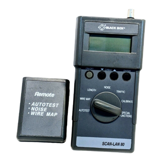
2.3 Controls The Scan-LAN 80 is operated with a rotary function selector and four pushbutton switches. See Figure 2-1. The Rotary Function Selector selects the operating mode (Autotest, Wire Map, Length, Noise, Traffic,... - Page 11 CHAPTER 2: Introduction The ON/OFF Button turns the power on or off. When no activity has been detected for five minutes, the Scan-LAN 80 will automatically power down to conserve battery power. Buttons select the cable type from a list of preset and user-defined types.
-
Page 12: Connectors
SCAN-LAN 80 CABLE SCANNER 2.4 Connectors The Scan-LAN 80 has two connectors: BNC and RJ- 45. BNC is a shielded connector for coax cable, and RJ-45 is a standard 8-pin modular jack for twisted- pair cable. See the figure below. -
Page 13: The Remote Unit
CHAPTER 2: Introduction 2.5 The Remote Unit The Scan-LAN 80 Remote Unit is connected at the far end of the cable when using Autotest to test twisted-pair cable. The Remote Unit, when used with the Scan-LAN 80, permits NEXT and attenuation measurements and allows connector wiring to be mapped. -
Page 14: Cable Tests
NVP of your cable can be measured to achieve maximum accuracy. See Chapter 5. 3.1.1 C ABLE ELECTION The correct cable type must be selected before performing any tests. The Scan-LAN 80 is programmed with six preset cable types. See Appendix A for more information. -
Page 15: Testing Twisted-Pair Cables
Plug the other end of the cable into the Remote Unit. Make sure that no cable is plugged into the BNC connector. To test a cable that is wired to jacks, use the RJ-45 patch cables between the jacks and the Scan-LAN 80 and/or Remote Unit. - Page 16 SCAN-LAN 80 CABLE SCANNER Twisted-Pair Cable Remote Unit Figure 3-1. Cable Testing. During Autotest, the Scan-LAN 80 will execute these tests: Background Noise, Wire Map, Length and Anomalies, NEXT, Attenuation, and Characteristic Impedance. Each test is described on the following...
- Page 17 CHAPTER 3: Cable Tests Noise The Noise test determines if background noise is present on the cable. A display of the test results, like the one below, will appear only if the test fails. Cable Fails Background Noise 25dB Press any key Wire Map This test verifies a correct wiring of all four pairs in a twisted-pair cable.
- Page 18 SCAN-LAN 80 CABLE SCANNER 1,2 Straight Thru 3,6 Straight Thru 4,5 Open 7,8 Open Wiring...
- Page 19 CHAPTER 3: Cable Tests 1,2 Open 3,6 Straight Thru 4,5 Open 7,8 Open Wiring...
- Page 20 SCAN-LAN 80 CABLE SCANNER 1,2 Shorted 3,6 Straight Thru 4,5 Open 7,8 Open Wiring...
- Page 21 CHAPTER 3: Cable Tests 1,2 Cross to 3,6 3,6 Cross to 1,2 4,5 Open 7,8 Open Wiring...
- Page 22 SCAN-LAN 80 CABLE SCANNER 1,2 Reversed 3,6 Reversed 4,5 Open 7,8 Open Wiring...
- Page 23 7,8 Open (unit unable to determine 1, 2 wiring) Wiring The Scan-LAN 80 verifies that the transmit and receive pairs for the selected LAN environment are present. Listed below are the transmit and receive pairs for Ethernet and Token Ring.
- Page 24 SNR Press any key This display means that because of faulty wiring, the Scan-LAN 80 cannot measure Signal to Noise Ratio, Near-End Crosstalk, or Attenuation. Length and characteristic impedance will be measured. Press any key to continue with Autotest.
- Page 25 If any anomalies are found, the anomalies and the cable length will be alternately flashed on the display. Anomalies are reflections from impedance mismatches located between the Scan-LAN 80 and the end of the cable. They can be caused by a faulty punchdown-block connection (twisted-pair networks) or badly crimped cables (coax networks).
- Page 26 Cable Fails NEXT 30dB @ 7 MHz Press any key If the Scan-LAN 80 measures crosstalk indicative of a split pair in the cable, the following screen appears. Split Pair!! Pair 1,2 splits...
- Page 27 CHAPTER 3: Cable Tests Attenuation Signal loss over the length of the cable is measured between 5 and 16 MHz. The highest attenuation (greatest loss) over the frequency range will be displayed. Attenuation is measured in a loopback mode between the transmit and receive pairs, but is displayed as end-to-end loss.
- Page 28 SCAN-LAN 80 CABLE SCANNER Characteristic Impedance Fails 13Ω Press any key Test Results After the Scan-LAN 80 has completed its cable tests, the unit displays a final screen containing important measurements for twisted-pair cables. Length 34dB OK for 10BaseT Cable Length is displayed in either feet or meters on the top line of the display.
-
Page 29: Testing Coax Cables
A larger number is better, indicating lower noise. A flashing SNR reading indicates a failing Signal-to-Noise Ratio. If the Scan-LAN 80 was unable to measure NEXT and attenuation because of a faulty wire map, SNR will be displayed as “N/A.”... - Page 30 SCAN-LAN 80 CABLE SCANNER Attach one end of the cable to the BNC connector on the Scan-LAN 80. Do not locate the Scan-LAN 80 in the middle of the cable. Attach a terminator of the correct value for the cable type to the other end of the cable.
- Page 31 CHAPTER 3: Cable Tests The Scan-LAN 80 performs the following tests during Autotest of coaxial cables: Background Noise, Characteristic Impedance, Termination Resistance, and Length and Anomalies. Each test is described on the following pages. Background Noise The Noise test is performed first to determine if background noise is present on the cable.
- Page 32 SCAN-LAN 80 CABLE SCANNER Characteristic Impedance Fails 93Ω Press any key Termination Resistance Termination resistance at the end of the cable is measured. The display below will appear if the termination resistance exceeds specified limits. Bad Termination Resistance 93Ω Press any key...
- Page 33 If the cable length exceeds the specified limit for the type of cable selected, the following display will appear. WARNING Cable Too Long Length: 445' Press any key Test Results At the conclusion of the Autotest, the Scan-LAN 80 will display the following important measurements for coaxial cables.
- Page 34 Terminator value in ohms is displayed. A flashing “Terminator” indicates a bad terminator. If the termination resistance is outside the range of the Scan-LAN 80, “OPEN” will be displayed. Impedance value in ohms is displayed. A flashing impedance value indicates a characteristic impedance value that does not meet specifications for the selected cable type.
-
Page 35: Individual Cable Tests
CHAPTER 3: Cable Tests Checking Multiple Cables The Scan-LAN 80 senses when a change occurs in the cable connection and restarts the test. Use this feature to easily test many cables—just plug in the new cable, and the test results will appear in several seconds. -
Page 36: Length Test
Unit. Test results will be shown in the display, with the location of any wiring errors noted (refer to Section 3.1). The Scan-LAN 80 will rerun the Wire Map test and update the display every two seconds. 3.2.2 L ENGTH... - Page 37 CHAPTER 3: Cable Tests Coax Cable Twisted-Pair Cable Set the rotary function selector to LENGTH. Press the button until the desired cable type is displayed. Make sure that any terminators are disconnected when testing coax cable. The Remote Unit is not required for testing length of twisted-pair cable.
- Page 38 (Coax) Any anomalies found will be flashed on the display. Anomalies are reflections from impedance mismatches located between the Scan-LAN 80 and the end of the cable. They can be caused by a faulty punchdown-block connection (twisted-pair networks) or badly crimped cables (coax networks).
-
Page 39: Noise Test
Chapter 6 if you want to change this value. Connect the cable to the appropriate connector on the Scan-LAN 80. The cable should not be connected to an active network; the test will record network traffic as noise impulses. - Page 40 SCAN-LAN 80 CABLE SCANNER For most accurate measurements, the cable should be properly terminated. If testing twisted-pair cable, plug the far end of the cable into the Remote Unit. For coax cable, connect a terminator to the far end of the cable.
- Page 41 CHAPTER 3: Cable Tests Terminator Coax Cable Set the rotary function selector to NOISE. Press the button until the desired cable type is displayed. After 10 seconds, the display will give a PASS or FAIL result for the test.
- Page 42 SCAN-LAN 80 CABLE SCANNER Noise Test: PASS Time 00:04:35 Average: 0.1/s Peak: 0.2/s Time shows the elapsed test time. Average shows the average noise impulses per second. PK (Peak) shows the worst-case 1-second average noise. NOTE For 10BASE-T cable, the maximum allowable impulse noise...
-
Page 43: Traffic Measurement
The unit also provides audio feedback of network activity. NOTE The traffic test runs continuously. The Scan-LAN 80 will automatically power down after 5 minutes. For 10BASE-T networks, the Scan-LAN 80 automatically generates link pulses to activate the hub and reports whenever a link with the hub is lost. - Page 44 SCAN-LAN 80 CABLE SCANNER 4 UTP, Token Ring 16 UTP, or Token Ring STP (non-Ethernet), the Scan-LAN 80 will display the following message: Incorrect CABLE selected for current test Token Ring4 UTP 4. If the correct cable type hasn’t been previously...
- Page 45 CHAPTER 4: Traffic Measurement The display will show a continuous reading of traffic conditions on the network. Listed below are explanations of the information that will appear in the display window. 1sec Traffic shows the average network utilization over the last second and gives an indication of current traffic levels.
- Page 46 SCAN-LAN 80 CABLE SCANNER If packets are detected which are longer than 20 ms, this display will remain until the problem is resolved. WARNING! JABBER DETECTED ON NETWORK 6. Select another test or turn the unit off when you want to stop the traffic test. The unit will automatically power down after five minutes.
-
Page 47: Cable Calibration
CHAPTER 5: Cable Calibration 5. Cable Calibration Any of the six supported cable types may be calibrated for a specific cable spool. The Calibrate Cable function lets you measure the NVP of a known length of cable and save it for additional measurements. - Page 48 SCAN-LAN 80 CABLE SCANNER 50' MINIMUM LENGTH Figure 5-1. Connecting Unterminated Cable.
- Page 49 CHAPTER 5: Cable Calibration Set the rotary function selector to CALIBRATE. Press the button to select the correct cable type, then press the ENTER button. and ENTER Cable Type: 10BaseT When the display below appears, set the actual length of the cable with the button, then press the ENTER button.
-
Page 50: Custom Setup
SCAN-LAN 80 CABLE SCANNER 6. Custom Setup 6.1 Where to Begin The units of length measurement, minimum fault threshold, and minimum noise threshold can be changed by the user. In addition, the audible tone can be enabled or disabled from the Custom Setup mode. -
Page 51: Units Of Length
CHAPTER 6: Custom Setup 6.2 Units of Length The currently selected units, feet or meters, will be shown in the display. and ENTER Units of length: feet Press the button until the display shows the desired length units. Press the Enter button to store the length units setting. -
Page 52: Fault Threshold
The fault threshold is the minimum reflection level detected as an anomaly in the AUTOTEST or LENGTH test. Any reflections less than this threshold will be ignored by the Scan-LAN 80. The threshold is expressed as a percentage of the incident test pulse. -
Page 53: Noise Threshold
CHAPTER 6: Custom Setup Press the button until the display shows the desired fault threshold. and ENTER Fault Threshold: Press the Enter button to store the fault threshold setting. 6.5 Noise Threshold The noise threshold is the minimum detection level for noise impulses measured in the NOISE test. -
Page 54: Saving/Resetting Changes
260 mV Press the Enter button to store the noise threshold. 6.6 Saving/Resetting Changes After all of the user-selectable settings have been entered, the Scan-LAN 80 will display the following: Dial new test OR ENTER to reset parameters OR to repeat Set the rotary selector to a new test function to save the entered settings. -
Page 55: Resetting To The Factory Settings
Custom Setup without deleting the changes just entered. 6.7 Resetting to the Factory Settings The Scan-LAN 80 may be reset to factory settings using the RESET TO DEFAULT function. All settings, including audible tones, the units of length,... - Page 56 ENTER Reset to Default Press the Enter button. press ENTER to reset all parameters to factory settings Press the Enter button to reset the Scan-LAN 80 to factory settings, or select another function using the rotary selector to abort.
-
Page 57: Maintenance
CHAPTER 7: Maintenance 7. Maintenance 7.1 Self-Test The Scan-LAN 80 includes a self-test function. Disconnect all cables and run this test periodically to assure that the unit is functioning properly. 1. Set the rotary function selector to SPECIAL FUNCTIONS. and ENTER Custom Setup 2. - Page 58 SCAN-LAN 80 CABLE SCANNER The display below will appear if all tests pass. CPU: PASS ROM: PASS RAM: PASS ANALOG: PASS 4. If any test fails, the unit will beep twice, then display the fault. CPU: PASS ROM: PASS RAM:...
-
Page 59: Power
7.2 Power 7.2.1 T -LAN 80 Power to the Scan-LAN 80 is supplied by the two 9-volt alkaline batteries. The battery compartment is accessed by sliding off the cover on the bottom of the unit. The Scan-LAN 80 will typically operate for at least 8 hours on a pair of batteries. -
Page 60: The Remote Unit
Power to the Remote Unit is applied only for brief intervals during cable tests, for minimal battery drain. The Scan-LAN 80 periodically tests remote operation and will warn the user when the remote battery needs replacement. -
Page 61: Appendix A: Standard Cable Types
APPENDIX A: Standard Cable Types Appendix A: Standard Cable Types The following cable types are included in the standard cable library resident in the Scan-LAN 80. Default NVP values may be altered with the CALIBRATE CABLE function. Designation Impedance Connector/Pairs... -
Page 62: Appendix B: Cable Test Pass/Fail Limits
(10BASE-T or Token Ring). The Autotest Results screen presented at the conclusion of Autotest indicates whether the cable meets IEEE specifi- cations. See Chapter 3 for more information. The next four pages contain the IEEE test limits used by the Scan-LAN 80 while testing twisted-pair cabling. - Page 63 APPENDIX B: Cable Test Pass/Fail Limits 10BASE-T Pass/Fail Limits 10BASE-T Test Limits Length Length < 100 meters Required Wire Pairs 1,2 and 3,6 Background Noise Background Noise > NEXT + 6 dB Between 5 and 10 MHz, SNR > 15 dB Characteristic Impedance 100±25 ohms NEXT...
- Page 64 SCAN-LAN 80 CABLE SCANNER Token Ring 4 UTP Pass/Fail Limits Token Ring 4 UTP Test Limits Length Length < 100 meters Required Wire Pairs 3,6 and 4,5 Background Noise Background Noise > NEXT + 6 dB Between 5 and 10 MHz, SNR ≥ 15 dB Characteristic Impedance 100±25 ohms...
- Page 65 APPENDIX B: Cable Test Pass/Fail Limits Token Ring 16 UTP Pass/Fail Limits Token Ring 16 UTP Test Limits Length Length < 100 meters Required Wire Pairs 3,6 and 4,5 Background Noise Background Noise > NEXT + 6 dB Between 5 and 16 MHz, SNR ≥ 24 dB Characteristic Impedance 100±25 ohms NEXT...
- Page 66 SCAN-LAN 80 CABLE SCANNER Token Ring STP Pass/Fail Limits Token Ring STP Test Limits Length Length < 100 meters Required Wire Pairs 3,6 and 4,5 Background Noise Background Noise > NEXT + 6 dB Between 5 and 16 MHz, SNR ≥ 24 dB Characteristic Impedance 100±25 ohms...
-
Page 67: Coaxial Cables
APPENDIX B: Cable Test Pass/Fail Limits B.2 Coaxial Cables The following charts show the Pass/Fail limits used by the Scan-LAN 80 while testing coaxial cables. ThinNet Pass/Fail Limits ThinNet Test Limits Length Length < 185 meters Background Noise Background Noise < 400 mV Characteristic Impedance 50±12 ohms... -
Page 68: Glossary
SCAN-LAN 80 CABLE SCANNER Glossary 10BASE2 — An IEEE standard for Thin Coax Ethernet networks; specifies 10-Mbps transmission, baseband signaling, 185 meters per coax segment. Also known as ThinNet or Cheapernet. 10BASE-T — An IEEE standard for unshielded twisted-pair Ethernet networks; specifies 10-Mbps transmission, baseband signaling, unshielded twisted- pair cable. - Page 69 GLOSSARY Characteristic Impedance — Resistance to AC current flow presented by a long cable. An AC parameter; not related to DC resistance. Coaxial Cable — A type of cable in which the inner conductor is surrounded by a tubular conductor, which acts as a shield.
- Page 70 SCAN-LAN 80 CABLE SCANNER Crosstalk — Noise coupled between pairs of wire in twisted-pair cable. dB — Abbreviation for “decibel,” a logarithmic unit of measure expressing the amplitude ratio between two signals. dB=20log( Vout ) Ethernet — A high-speed LAN using Carrier Sense Multiple Access with Collision Detection (CSMA/CD).
- Page 71 GLOSSARY Nominal Velocity of Propagation (NVP) — The speed of signal propagation through a cable, expressed as a percentage of the speed of light in a vacuum. Open — A break in the continuity of a circuit, preventing signal transmission. Packet —...
- Page 72 SCAN-LAN 80 CABLE SCANNER RJ-45 — An 8-position telephone-type modular connector used with twisted-pair cable. Runt Packet — An Ethernet data packet which is shorter than the valid minimum packet length (64 bytes). Usually caused by a collision. Segment — A network cable terminated at both ends.
- Page 73 GLOSSARY but because the transmission circuit is split between two twisted pairs, excessive crosstalk occurs. Split Pairs TDR (Time-Domain Reflectometry) — A technique for measuring cable lengths by timing the duration between an incident test pulse and the reflected pulse from an impedance mismatch on the cable (such as an open at the end of the cable).
- Page 74 SCAN-LAN 80 CABLE SCANNER Terminator — A resistor connected to the end of a coax cable that is intended to match the characteristic impedance of the cable. Signals propagating down the cable are dissipated in the terminator, eliminating reflections from the end of the cable.
-
Page 75: Index
INDEX Index Buttons......7 Custom setup......46 10BASE-T, traffic test ...39 ENTER button .......7 1sec Traffic ......41 Ethernet, Anomalies.......21, 28 transmit/receive pairs..19 Attenuation ......23 Factory settings, Audible tone, resetting to......51 enable/disable....47 Fault threshold.....48 Autotest.........10 Features ........6 Background noise ....27 IEEE test limits .....58 Bar graph......41 Impedance value....30 Batteries......55, 56... - Page 76 SCAN-LAN 80 CABLE SCANNER Peak traffic......41 Testing, Token Ring Power, remote unit ....56 16 UTP ......61 Power, Scan-LAN 80 ....55 Testing, Token Ring Remote unit......56 4 UTP ......60 Remote unit, general .....9 Testing, Token Ring Rotary function selector ..6 STP ........62 Scan-LAN 80, Threshold, fault ....48...
Need help?
Do you have a question about the Scan-LAN 80 and is the answer not in the manual?
Questions and answers