Table of Contents
Advertisement
Available languages
Available languages
Quick Links
Advertisement
Chapters
Table of Contents

Related Manuals for Zehnder Rittling RF55


Summary of Contents for Zehnder Rittling RF55
- Page 1 Decorative Radiators Comfortable Indoor Ventilation Heating & Cooling Ceiling Systems Clean Air Solutions Zehnder CO Sensor Installatiehandleiding Installation manual Installationshandbuch Manuel d’installation Manuale d’installazione Instrukcja montażu Manual de instalación...
- Page 2 Contents NL ..........................3 EN ...........................24 DE ...........................45 FR ...........................66 IT ..........................87 PL ..........................108 ES .........................129 2 - NL...
-
Page 3: Voorwoord
Voorwoord Lees dit document voor gebruik Alle rechten voorbehouden zorgvuldig door. Deze installatiehandleiding is met de grootste zorgvuldigheid samengesteld. Deze installatiehandleiding bevat alle De uitgever kan echter niet verantwoorde benodigde informatie voor een veilige en lijk worden gehouden voor enige schade juiste installatie van deze CO Sensor. -
Page 4: Table Of Contents
Inhoud Voorwoord ...................... 3 1. Uitpakken en voorbereiden van de installatie ..........6 1.1 Inhoud van de doos ................6 1.2 Controle van de levering ................. 7 1.3 Benodigd gereedschap en montagemateriaal .......... 7 2. Beschrijving en herkenning ................8 2.1 Algemeen .................... - Page 5 6. Installatie CO Sensor type 0-10V ............... 18 6.1 Algemeen ..................... 18 6.2 Installatie CO Sensor type 0-10V ............18 6.3 Instellingscontrole CO Sensor type 0-10V ..........19 7. Inbedrijfstelling ................... 20 7.1 Voorwaarden voor het juist functioneren van de CO Sensor ....
-
Page 6: Uitpakken En Voorbereiden Van De Installatie
1. Uitpakken en voorbereiden van de installatie 1.1 Inhoud van de doos Model Inhoud doos Sensor RF55 (230V) ■ 4x kap Sensor 010V55 ■ 1x CO Sensor ■ 1x transparant montageframe ■ 1x venster ■ 2x schroeven Sensor RF67 (230V) ■... -
Page 7: Controle Van De Levering
Model Inhoud doos Sensor RF67 onwall (230V) ■ 1x kap Sensor 010V67 onwall ■ 1x CO Sensor ■ 1x montageframe ■ 1x opbouwdoos ■ 8x schroeven ■ 2x pluggen 1.2 Controle van de levering 1. Controleer of de verpakking niet beschadigd is. 2. -
Page 8: Beschrijving En Herkenning
CO Sensor die de hoogste ventilatiestand doorgeeft aan het ventilatiesysteem. 2.2 Uitvoeringen Type Voeding Variant Model/naam 55mm inbouw Sensor RF55 (230V) RF* (Radio 230V AC Frequentie) 67mm inbouw Sensor RF67 (230V) 67mm opbouw Sensor RF67 onwall (230V) 55mm inbouw Sensor 010V55... -
Page 9: Combinatiemogelijkheden
2.3 Combinatiemogelijkheden Bij ieder gebruik van een schakelaar gebruikt de automatische ventilatieregeling deze zelfgekozen instelling gedurende maximaal 12 uur. Bij deze zelfgekozen mate van ventileren heeft de gemeten CO waarde geen invloed op het ventilatiesysteem. Combineer alleen onderstaande schakelaars met CO Sensoren. -
Page 10: Veiligheid
3. Veiligheid 3.1 Veiligheid met betrekking tot montage en installatie Gevaarlijke elektrische spanning! Levens of letselgevaar door elektrische spanning van 230V. W erkzaamheden aan het 230Vnet mo ■ gen uitsluitend worden uitgevoerd door erkende elektrotechnische installateurs. M aak het apparaat spanningsloos voordat ■... -
Page 11: Montagevoorschriften
Volg altijd de plaatselijke veiligheids voorschriften tijdens het monteren an het apparaat. Controleer het apparaat op beschadigingen door transport. Controleer dat de netspanning overeen komt met de lokale netspanning. 3.2 Montagevoorschriften Zorg dat het apparaat niet bedekt wordt, zodat de luchtkwaliteit Monteer de CO Sensor nooit in gemeten kan worden. -
Page 12: Installatievoorschriften Co Sensor Type 0-10V
De RFkoppeling met een ventila De garantie vervalt als: tietoestel werkt alleen, wanneer de ■ e en defect het gevolg is van Sensor binnen het bereik van onbedoeld of onvoorzichtig dit toestel is geplaatst. Bij gebruik gebruik van het apparaat; van meerdere sensoren moet ■ e en defect het gevolg is van vervuiling tenminste één CO... -
Page 13: Montage
4. Montage 4.1 Weergave van de onderdelen Exploded view Sensor RF55 (230V) & Sensor 010V55 * Optioneel ** Wordt niet meegeleverd Figuur 4.1 CO Sensor RF55 & 010V55 Sensor RF67 (230V) & Sensor 010V67 Figuur 4.2 CO Sensor RF67 & 010V67 Sensor RF67 onwall (230V) &... - Page 14 Aansluiting Figuur 4.4 Achterzijde CO Sensor type RF 010V Figuur 4.5 Achterzijde CO Sensor type 010V 14 - NL...
-
Page 15: Montage Van De Co Sensor Type 0-10V
4.2 Montage van de CO Sensor 4.3 Montage van de CO Sensor type 0-10V type RF Alle letters in dit hoofdstuk verwijzen naar Alle letters in dit hoofdstuk verwijzen naar de voorgaande afbeeldingen. de voorgaande afbeeldingen. 1. Bevestig bij de onwallsensor de 1. -
Page 16: Installatie Co Sensor Type Rf
5. Installatie CO Sensor type RF 5.1 Algemeen De CO Sensor type RF is altijd ingesteld als regelaar. De CO Sensor type RF moet vóór het eerste gebruik worden gekoppeld aan het ventilatietoestel. Druk tijdens de installatie telkens binnen 30 seconden op de bedieningsknop van de CO Sensor om een keuze te bevestigen. - Page 17 Bij een actieve koppelingsstand ■ D e bovenste led kleurt rood: dit is op een ventilatietoestel is er de koppelingsmodus om een nieuw 10 minuten de tijd om één CO RFadres te genereren voor het Sensor te koppelen. Bij elke ventilatietoestel.
-
Page 18: Installatie Co Sensor Type 0-10V
6. Installatie CO Sensor type 0-10V 6.1 Algemeen De functie van de CO Sensor type 010V dient vóór gebruik ingesteld te worden als regelaar of sensor. Is de CO Sensor ingesteld als sensor, dan meet deze alleen de CO waarden en geeft deze door aan het ventilatietoestel. -
Page 19: Instellingscontrole Co 2 Sensor Type 0-10V
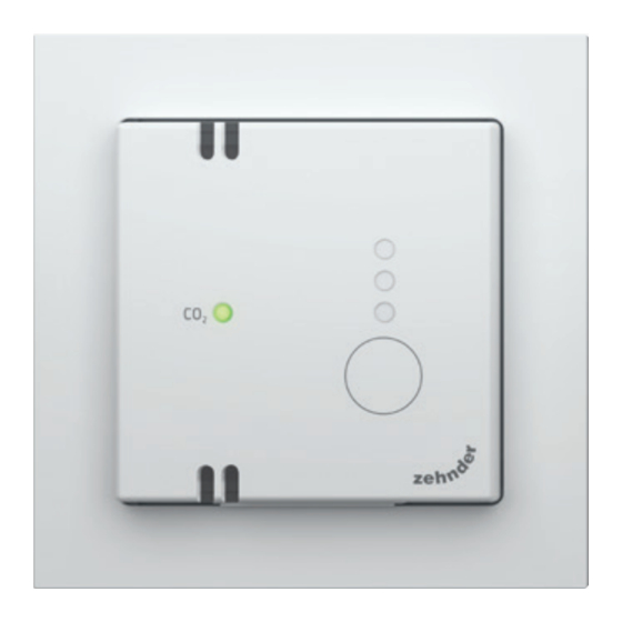
3. Druk kort op de bedieningsknop om de juiste functie te selecteren: ■ F unctie regelaar: De CO led wordt groen, de onderste twee ledjes rechts worden rood. ■ F unctie sensor: De CO led wordt rood, de onderste twee ledjes rechts worden rood. -
Page 20: Inbedrijfstelling
7. Inbedrijfstelling 7.1 Voorwaarden voor het juist functioneren van de CO Sensor ■ Z org dat het apparaat niet bedekt wordt, zodat de luchtkwaliteit gemeten kan worden. ■ Z org voor voldoende luchttoevoer. Open hiervoor bijvoorbeeld een klapraam of aan wezige ventilatieroosters in de ramen, kozijnen of schuifpui. -
Page 21: Helderheid Ledjes Instellen
7.3 Helderheid ledjes instellen 3. Druk gedurende 5 seconden op de bedieningsknop, om in het menu voor Druk tijdens de installatie telkens helderheid te komen: binnen 30 seconden op de bedie ■ A lle ledjes knipperen 3x groen. ningsknop van de CO Sensor om een keuze te bevestigen. -
Page 22: Storingen
8. Storingen 8.1 Storingen van de CO Sensor type RF Storing Probleem Oplossing Na een druk op de bevestigings ■ De CO Sensor is nog Koppel de CO Sensor aan het knop geeft de CO led het ventilatietoestel. Raadpleeg niet gekoppeld aan een niveau weer. -
Page 23: Onderhoud
9. Onderhoud Verwijder regelmatig stof met een droge stofdoek of heel voorzichtig met een stofzuiger. Reinig het apparaat nooit met vocht. Gebruik nooit reinigingsmiddelen. 10. Demontage en verwijdering Als de CO Sensor wordt gedemonteerd, dan moeten de voorschriften voor afval verwerking in acht worden genomen die ter plaatse en ten tijde van de demontage gelden. -
Page 24: Foreword
Foreword Please read this document All rights reserved carefully before use. This installation manual has been compiled with the utmost care. This installation manual contains all the However, the publisher cannot be held necessary information for a safe and correct responsible for any damage caused by failu... - Page 25 Contents Foreword ....................... 24 1. Unpacking and preparing the installation ............. 27 1.1 Contents of the box ................27 1.2 Checking the delivery ................28 1.3 Required tools and mounting materials ..........28 2. Description and identification ..............29 2.1 General ....................29 2.2 Versions ....................
- Page 26 6. Installation of the CO 0-10V Sensor ............39 6.1 General ....................39 6.2 Installation of the CO 0-10V Sensor ............39 6.3 Control setting of the CO 0-10V Sensor ..........40 7. Commissioning ..................41 7.1 Prerequisites for the correct functioning of the CO Sensor .....
-
Page 27: Unpacking And Preparing The Installation
1. Unpacking and preparing the installation 1.1 Contents of the box Model Box Contents RF55 Sensor (230V) ■ 4x cover 010V55 Sensor ■ 1x CO Sensor ■ 1x transparent mounting frame ■ 1x window ■ 2x screws RF67 Sensor (230V) ■... -
Page 28: Checking The Delivery
Model Box Contents RF67 onwall Sensor (230V) ■ 1x cover 010V67 onwall Sensor ■ 1x CO Sensor ■ 1x mounting frame ■ 1x surfacemounted box ■ 8x screws ■ 2x plugs 1.2 Checking the delivery 1. Check that the packaging is not damaged. 2. -
Page 29: Description And Identification
Sensor that transmits the highest ventilation requirement to the ventilation system. 2.2 Versions Type Power Variant Model/name 55mm installation RF55 Sensor (230V) RF* (Radio 230V AC Frequency) 67mm installation RF67 Sensor (230V) 67mm assembly RF67 onwall Sensor (230V) 55mm installation 010V55 Sensor... -
Page 30: Combination Possibilities
2.3 Combination possibilities Whenever a switch is used, the automatic ventilation control uses this selfselected setting for a maximum of 12 hours. At this selfselected ventilation rate the measured value does not influence the ventilation system. Only combine the switches below with CO Sensors. -
Page 31: Safety
3. Safety 3.1 Safety regarding assembly and installation Dangerous electrical voltage! Risk of death or injury due to 230V electrical voltage. W ork on the 230V mains must only be ■ carried out by qualified electricians. D isconnect the device from the power supply ■... -
Page 32: Assembly Instructions
Always follow local safety regulations during assembly of the device. Check the device for damage caused by transport. Check that the mains voltage corresponds to the local mains voltage. 3.2 Assembly instructions Make sure that the device is not covered so that the air quality can be Never install the CO Sensor in toilets measured. -
Page 33: Installation Instructions Co 0-10V Sensor
The RF link to a ventilation unit The warranty is void if: will only work if the CO Sensor is ■ a defect is the result of inexpert or placed within range of this unit. If careless use of the device; several sensors are used, at least ■ a defect resulting from contaminating the one CO... -
Page 34: Assembly
4. Assembly 4.1 View of the components Exploded view Sensor RF55 (230V) & Sensor 010V55 * Optional ** Not included Figure 4.1 CO Sensor RF55 & 010V55 Sensor RF67 (230V) & Sensor 010V67 Figure 4.2 CO Sensor RF67 & 010V67 Sensor RF67 onwall (230V) &... - Page 35 Connection Figure 4.4 Rear side of the CO RF Sensor 010V Figure 4.5 Rear side of the CO 010V Sensor 35 - EN...
-
Page 36: Mounting Of The Co 0-10V Sensor
4.2 Mounting of the CO 0-10V Sensor 4.3 Mounting of the CO RF Sensor All letters in this section refer to the previous All letters in this section refer to the previous images. images. 1. At the onwall sensor, attach the 1. -
Page 37: Installation Of The Co Rf Sensor
5. Installation of the CO RF Sensor 5.1 General The CO RF Sensor is always set as the controller. The CO RF Sensor must be paired with the ventilation unit before first use. Within 30 seconds during installation, press the operating button of the CO Sensor to confirm a setting. - Page 38 With an active pairing mode ■ T he top LED turns red: this is the on a ventilation unit, there are pairing mode to generate a new 10 minutes to pair one CO Sensor. RF address for the ventilation unit. For each additional CO Sensor to be Previouslyregistered units must then paired, the ventilation unit must be...
-
Page 39: Installation Of The Co 0-10V Sensor
6. Installation of the CO 0-10V Sensor 6.1 General The function of the CO 010V Sensor must be set as a controller or sensor before use. If the CO Sensor is set up as a sensor, it only measures the CO values and transmits them to the ventilation unit. -
Page 40: Control Setting Of The Co 0-10V Sensor
3. Briefly press the operating button to select the correct function: ■ C ontroller function: The CO LED turns green; the bottom two LEDs on the right turn red. ■ S ensor function: The CO LED turns red; the bottom two LEDs on the right turn red. 4. -
Page 41: Commissioning
7. Commissioning 7.1 Prerequisites for the correct functioning of the CO Sensor ■ M ake sure that the device is not covered so that the air quality can be measured. ■ E nsure sufficient air supply. To do this, for example, open a hinged window or existing ventilation grilles in the windows, window frames or sliding doors. -
Page 42: Led Brightness Setting
7.3 LED brightness setting 3. Press the operating button for 5 seconds to enter the brightness menu: Within 30 seconds during installation, ■ A ll LEDs blink green 3 times. press the operating button of the Sensor to confirm a setting. 4. -
Page 43: Malfunctions
8. Malfunctions 8.1 Malfunctions of the CO RF Sensor Fault Problem Solution After pressing the confirmation Pair the CO Sensor to the ventila ■ The CO Sensor is not yet button, the CO LED displays tion unit. Refer to section 4 for the paired with a ventilation unit. -
Page 44: Maintenance
9. Maintenance Regularly remove dust with a dry duster or very carefully with a vacuum cleaner. Never clean the device with any moisture. Never use cleaning agents. 10. Disassembly and disposal If the CO Sensor is disassembled, the waste disposal regulations applicable onsite and at the time of disassembly must be observed. -
Page 45: Vorwort
Vorwort Bitte lesen Sie dieses Dokument Alle Rechte vorbehalten vor der Verwendung sorgfältig Dieses Installationshandbuch wurde mit durch. äußerster Sorgfalt zusammengestellt Der Herausgeber kann jedoch nicht für Schäden Dieses Installationshandbuch enthält verantwortlich gemacht werden, die durch alle notwendigen Informationen für die Nichtbeachtung von Sicherheits... - Page 46 Inhalt Vorwort ......................45 1. Auspacken und Vorbereiten der Installation ..........48 1.1 Inhalt des Kartons ................. 48 1.2 Überprüfung der Lieferung ..............49 1.3 Erforderliche Werkzeuge und notwendiges Montagematerial ....49 2. Beschreibung und Erkennung ..............50 2.1 Allgemein ..................... 50 2.2 Ausführungen ..................
- Page 47 6. Installation CO Sensor Typ 0-10V ............... 60 6.1 Allgemein ..................... 60 6.2 Installation CO Sensor Typ 0-10V ............60 6.3 Überprüfung der Installation des CO Sensors Typ 0-10V ....... 61 7. Inbetriebnahme ..................62 7.1 Voraussetzungen für das korrekte Funktionieren des CO Sensors ..
-
Page 48: Auspacken Und Vorbereiten Der Installation
1. Auspacken und Vorbereiten der Installation 1.1 Inhalt des Kartons Modell Inhalt des Kartons Sensor RF55 (230V) ■ 4x Abdeckung Sensor 010V55 ■ 1x CO Sensor ■ 1x transparenter Montagerahmen ■ 1x Fenster ■ 2x Schrauben Sensor RF67 (230V) ■ 1x Abdeckung Sensor 010V67... -
Page 49: Überprüfung Der Lieferung
Modell Inhalt des Kartons Sensor RF67 onwall (230V) ■ 1x Abdeckung Sensor 010V67 onwall ■ 1x CO Sensor ■ 1x Montagerahmen ■ 1x Wandmontagegehäuse ■ 8x Schrauben ■ 2x Stecker 1.2 Überprüfung der Lieferung 1. Prüfen Sie, ob die Verpackung nicht beschädigt ist. 2. -
Page 50: Beschreibung Und Erkennung
Sensoren aktiv, die als Regler eingerichtet sind? Der Grad der Lüftung basiert dann auf dem CO Sensor, der die höchste Lüftungsstufe an das Lüftungssystem übermittelt. 2.2 Ausführungen Versorgung Variante Modell/Name 55 mmEinbau Sensor RF55 (230V) RF* (Funkfre 230V Wechselstrom quenz) 67 mmEinbau Sensor RF67 (230V) 67mmKonstruktion Sensor RF67 onwall (230V) 55 mmEinbau... -
Page 51: Kombinationsmöglichkeiten
2.3 Kombinationsmöglichkeiten Immer wenn ein Schalter verwendet wird, verwendet die automatische Lüftungssteuerung diese selbst gewählte Einstellung für maximal 12 Stunden. Bei diesem selbst eingestellten Lüftungsgrad hat der gemessene CO Wert keinen Einfluss auf das Lüftungssystem. Kombinieren Sie nur die unten stehenden Schalter mit CO Sensoren. -
Page 52: Sicherheit
3. Sicherheit 3.1 Sicherheit in Bezug auf Montage und Installation Gefährliche elektrische Spannung! Lebensgefahr oder Verletzungsgefahr durch elektrische Spannung von 230V. A rbeiten am 230VNetz dürfen nur von ■ qualifizierten Elektrikern durchgeführt werden. T rennen Sie das Gerät von der Stromver ■... -
Page 53: Montageanleitung
Beachten Sie bei der Montage dieses Geräts stets die örtlichen Sicherheitsvorschriften. Überprüfen Sie das Gerät auf Transportschäden. Prüfen Sie, ob die Netzspannung mit der örtlichen Netzspannung übereinstimmt. 3.2 Montageanleitung Stellen Sie sicher, dass das Gerät nicht abgedeckt ist, damit die Installieren Sie den CO Sensor Luftqualität gemessen werden kann. -
Page 54: Installationsanweisungen Co Sensor Typ 0-10V
Die RFVerbindung zu einer Die Garantie verfällt, wenn: Lüftungseinheit funktioniert nur, ■ e in Defekt das Ergebnis eines wenn der CO Sensor in Reichweite unsachgemäßen oder unachtsamen dieses Geräts angebracht wird. Gebrauchs des Geräts ist; Wenn mehrere Sensoren verwendet ■ e in Defekt durch Verschmutzung des werden, muss mindestens ein Geräts entstanden ist;... -
Page 55: Montage
4. Montage 4.1 Anzeige der Teile Explosionszeichnung Sensor RF55 (230V) & Sensor 010V55 * Optional ** Wird nicht mitgeliefert Abbildung 4.1 CO Sensor RF55 & 010V55 Sensor RF67 (230V) & Sensor 010V67 Abbildung 4.2 CO Sensor RF67 & 010V67 Sensor RF67 onwall (230V) &... - Page 56 Anschluss Abbildung 4.4 Rückseite CO Sensor Typ RF 010V Abbildung 4.5 Rückseite CO Sensor Typ 010V 56 - DE...
-
Page 57: Montage Des Co Sensors Des Typs 0-10V
4.2 Montage des CO Sensors des 4.3 Montage des CO2 Sensors Typ RF Typs 0-10V Alle Buchstaben in diesem Kapitel beziehen Alle Buchstaben in diesem Kapitel beziehen sich auf die vorangehend angeführten sich auf die vorangehend angeführten Abbildungen. Abbildungen. 1. Trennen Sie die Netzspannung. 1. -
Page 58: Installation Co Sensor Typ Rf
5. Installation CO Sensor Typ RF 5.1 Allgemein Der CO Sensor Typ RF ist immer als Regler eingestellt. Der CO Sensor Typ RF muss vor dem ersten Gebrauch mit der Lüftungseinheit gekoppelt werden. Drücken Sie während der Installation jeweils innerhalb von 30 Sekunden die Steuertaste des CO Sensors, um eine Auswahl zu bestätigen. - Page 59 Bei einer aktiver Kopplung an eine ■ D ie obere LED leuchtet rot: Dies ist Lüftungseinheit gibt es 10 Minu die Kopplung zur Generierung einer ten Zeit um einen CO Sensor zu neuen RFAdresse für die Lüftungs koppeln. Für jeden nächsten zu einheit.
-
Page 60: Installation Co Sensor Typ 0-10V
6. Installation CO Sensor Typ 0-10V 6.1 Allgemein Die Funktion des CO Sensors Typ 010V muss noch vor der Verwendung als Regler oder Sensor eingestellt werden. Wenn der CO Sensor als Sensor eingerichtet ist, misst er nur die CO Werte und übermittelt diese an die Lüftungseinheit. -
Page 61: Sensors Typ 0-10V
3. Drücken Sie kurz auf die Steuertaste, um die richtige Funktion auszuwählen: ■ F unktion Regler: Die CO LED leuchtet grün, die unteren beiden LEDs rechts leuchten rot. ■ F unktion Sensor: Die CO LED leuchtet rot, die unteren beiden LEDs rechts leuchten rot. -
Page 62: Inbetriebnahme
7. Inbetriebnahme 7.1 Voraussetzungen für das korrekte Funktionieren des CO Sensors ■ S tellen Sie sicher, dass das Gerät nicht abgedeckt ist, damit die Luftqualität gemessen werden kann. ■ S tellen Sie eine ausreichende Luftzufuhr sicher. Öffnen Sie dazu z.B. ein Klappfenster oder vorhandene Lüftungsgitter in den Fenstern, Fensterrahmen oder Schiebetüren. -
Page 63: Einstellung Der Led-Helligkeit
7.3 Einstellung der LED-Helligkeit 3. Drücken Sie die Steuertaste 5 Sekunden lang, um in das Helligkeitsmenü zu Drücken Sie während der Installation gelangen: jeweils innerhalb von 30 Sekunden ■ A lle LED's blinken 3x grün. die Steuertaste des CO Sensors, um eine Auswahl zu bestätigen. -
Page 64: Funktionsstörungen
8. Funktionsstörungen 8.1 Funktionsstörungen des CO Sensors Typ RF Störungen Problem Lösung Nachdem Sie die Bestätigungs ■ Der CO Sensor ist noch Schließen Sie den CO Sensor taste gedrückt haben, zeigt die an die Lüftungseinheit an. nicht an eine Lüftungseinheit LED den CO Wert an. -
Page 65: Wartung
9. Wartung Wischen Sie den Staub regelmäßig mit einem trockenen Tuch ab oder saugen Sie ihn ganz vorsichtig mit einem Staubsauger Reinigen Sie das Gerät niemals feucht. Verwenden Sie niemals Reinigungsmittel. 10. Demontage und Entsorgung Bei der Entsorgung des CO Sensors sind die vor Ort und zum Zeitpunkt der Demontage geltenden Abfallentsorgungs... -
Page 66: Avant-Propos
Avant-propos Veuillez lire attentivement le Tous droits réservés le document suivant avant Le présent manuel a été rédigé avec le plus utilisation. grand soin. L'éditeur ne peut cependant être tenu Le manuel d’installation suivant contient responsable des dommages causés par toutes les informations nécessaires pour le nonrespect des consignes de sécurité... - Page 67 Contenu Avant-propos ....................66 1. Déballage et préparation de l’installation ............69 1.1 Contenu de la boîte ................69 1.2 Vérification de la livraison ..............70 1.3 Outils et matériel de montage nécessaires ..........70 2. Description et reconnaissance..............71 2.1 Généralités ...................
- Page 68 6. Installation du capteur de CO type 0-10 V ..........81 6.1 Généralités ................... 81 6.2 Installation du capteur de CO type 0-10 V ..........81 6.3 Contrôle du réglage du capteur de CO type 0-10 V ....... 82 7. Mise en service ..................83 7.1 Conditions requises pour le bon fonctionnement du capteur de CO ..
-
Page 69: Déballage Et Préparation De L'installation
1. Déballage et préparation de l’installation 1.1 Contenu de la boîte Modèle Contenu de la boîte Capteur de CO RF55 (230 V) ■ Quatre caches Capteur de CO 010 V55 ■ Un capteur de CO ■ Un cadre de montage transparent ■ Une fenêtre ■... -
Page 70: Vérification De La Livraison
Modèle Contenu de la boîte Capteur de CO RF67 mural (230 V) ■ Un cache Capteur de CO 010 V67 mural ■ Un capteur de CO ■ Un cadre de montage ■ Un boîtier de montage ■ Huit vis ■ Deux chevilles 1.2 Vérification de la livraison 1. -
Page 71: Description Et Reconnaissance
élevé au système de ventilation. 2.2 Modèles Type Alimentation Variante Modèle/nom À intégrer, 55 mm Capteur de CO RF55 (230 V) RF* (radiof 230 V c.a. réquence) À intégrer, 67 mm Capteur de CO RF67 (230 V) À poser, 67 mm Capteur de CO RF67 mural (230 V) -
Page 72: Associations Possibles
2.3 Associations possibles À chaque utilisation d’un interrupteur, le réglage automatique de la ventilation utilise ce réglage automatiquement sélectionné pendant 12 heures maximum. La valeur de CO mesurée n’a alors aucun impact sur le système de ventilation. Seuls les interrupteurs suivants peuvent être associés à des capteurs de CO Aspect Modèle/nom Zehnder RFZ... -
Page 73: Sécurité
3. Sécurité 3.1 Sécurité lors du montage et de l’installation Tension électrique dangereuse ! Risque de décès ou de blessure dû à la tension électrique de 230 V L es travaux sur le réseau de 230 V ■ ne doivent être effectués que par des électriciens qualifiés. -
Page 74: Consignes De Montage
Suivez toujours les consignes de sécurité locales lors du montage de l’appareil. Vérifiez que l’appareil n’a pas été endommagé lors du transport. Vérifiez que la tension correspond à la tension secteur locale. 3.2 Consignes de montage Veillez à ce que l’appareil ne soit pas recouvert afin qu’il puisse mesurer la N’installez jamais le capteur de CO qualité... -
Page 75: Type 0-10 V
Le couplage RF avec un dispositif La garantie s’annule dans les cas suivants : de ventilation ne fonctionne que si le ■ l e défaut résulte d’une utilisation capteur de CO est installé à portée inadaptée ou imprudente de l’appareil, du dispositif. -
Page 76: Montage
4. Montage 4.1 Représentation des pièces Vue éclatée Sensor RF55 (230 V) et Sensor 010 V55 * Facultatif ** Non inclus Illustration 4.1 CO Sensor RF55 et 010 V55 Sensor RF67 (230 V) et Sensor 010 V67 Illustration 4.2 CO Sensor RF67 et 010 V67 Sensor RF67 onwall (230 V) et Sensor 010 V67 onwall... - Page 77 Connexion Illustration 4.4 Partie arrière du capteur de CO type RF 010 V Illustration 4.5 Partie arrière du capteur de CO type 010 V 77 - FR...
-
Page 78: Type 0-10 V
4.2 Montage du capteur de CO type 4.3 Montage du capteur de CO type 0-10 V Toutes les lettres du présent chapitre font Toutes les lettres du présent chapitre font référence aux illustrations précédentes. référence aux illustrations précédentes. 1. Fixez le boîtier de montage du capteur 1. -
Page 79: Installation Du Capteur De Co Type Rf
5. Installation du capteur de CO type RF 5.1 Généralités Le capteur de CO type RF est toujours configuré en tant que régulateur. Le capteur de CO type RF doit être couplé au dispositif de ventilation avant la première utilisation. Lors de l’installation, appuyez sur le bouton de commande du capteur de CO dans les 30 secondes qui suivent pour confirmer la sélection. - Page 80 Une fois le mode de couplage activé ■ L a LED supérieure s’allume en sur un dispositif de ventilation, rouge : il s’agit du mode de couplage vous avez dix minutes pour coupler qui permet de générer une nouvelle un capteur de CO .
-
Page 81: Type 0-10 V
6. Installation du capteur de CO type 0-10 V 6.1 Généralités Le capteur de CO type 010 V doit être configuré en tant que régulateur ou en tant que capteur avant utilisation. Si le capteur de CO est configuré en tant que capteur, il mesure que les valeurs de CO et les transmet au dispositif de ventilation. -
Page 82: Contrôle Du Réglage Du Capteur De Co Type 0-10 V
3. Appuyez brièvement sur le bouton de commande pour sélectionner la fonction correcte : ■ F onction régulateur : la LED CO s’allume en vert, les deux LED du bas s’allument en rouge. ■ F onction capteur : la LED CO s’allume en rouge, les deux LED du bas s’allument en rouge. -
Page 83: Mise En Service
7. Mise en service 7.1 Conditions requises pour le bon fonctionnement du capteur de CO ■ V eillez à ce que l’appareil ne soit pas recouvert afin qu’il puisse mesurer la qualité de l’air. ■ V eillez à ce que l’alimentation en air soit suffisante. Pour ce faire, vous pouvez ouvrir une fenêtre basculante ou les grilles d’aération au niveau des fenêtres, des encadrements ou des baies vitrées. -
Page 84: Réglage De La Luminosité Des Led
7.3 Réglage de la luminosité des LED 3. Appuyez sur le bouton de commande pendant cinq secondes pour accéder au Lors de l’installation, appuyez sur le menu de la luminosité : bouton de commande du capteur ■ T outes les LED clignotent trois fois en de CO dans les 30 secondes qui vert. -
Page 85: Dysfonctionnements
8. Dysfonctionnements 8.1 Dysfonctionnements du capteur de CO type RF Dysfonctionnement Problème Solution Lorsque vous appuyez sur le Couplez le capteur de CO ■ Le capteur de CO n’est pas bouton de confirmation, la LED au dispositif de ventilation. encore couplé à un dispositif affiche de nouveau le niveau Reportezvous au chapitre 4 pour de ventilation. -
Page 86: Entretien
9. Entretien Retirez régulièrement la poussière à l’aide d’un chiffon sec ou avec un aspirateur (procédez alors très délicatement). Ne mouillez jamais l’appareil pour le nettoyer. N’utilisez jamais de produits de nettoyage. 10. Démontage et mise au rebut Si le capteur de CO est démonté, il convient de respecter les consignes d’élimination des déchets applicables sur le... -
Page 87: Premessa
Premessa Leggere attentamente il presente Tutti i diritti riservati documento prima dell'uso. Il presente manuale d'installazione è stato compilato con la massima cura. Questo manuale d'installazione contiene Tuttavia l'editore non può essere ritenuto tutte le informazioni necessarie per un'in responsabile per eventuali danni causati stallazione corretta e sicura del sensore dalla mancata osservanza delle istruzioni di CO... - Page 88 Sommario Premessa ...................... 87 1. Disimballaggio e preparazione dell'installazione ........... 90 1.1 Contenuto della scatola ................. 90 1.2 Verifica della fornitura ................91 1.3 Utensili e materiale di montaggio necessari ..........91 2. Descrizione e identificazione ..............92 2.1 Descrizione generale ................92 2.2 Versioni ....................
- Page 89 6. Installazione del Sensore CO tipo 0-10V ........... 102 6.1 Descrizione generale ................102 6.2 Installazione del Sensore CO tipo 0-10V ..........102 6.3 Controllo delle impostazioni del sensore CO tipo 0-10V ....... 103 7. Messa in servizio..................104 7.1 Prerequisiti per il corretto funzionamento del sensore di CO ....
-
Page 90: Disimballaggio E Preparazione Dell'installazione
1. Disimballaggio e preparazione dell'installazione 1.1 Contenuto della scatola Modello Contenuto della scatola Sensore di CO RF55 (230V) ■ 4x frontalino Sensore di CO 010V55 ■ 1x sensore di CO ■ 1x telaio di montaggio trasparente ■ 1x finestra ■ 2x viti... -
Page 91: Verifica Della Fornitura
Modello Contenuto della scatola Sensore di CO RF67 a parete ■ 1x frontalino (230V) ■ 1x sensore di CO Sensore di CO 010V67 a parete ■ 1x telaio di montaggio ■ 1x scatola di montaggio a superficie ■ 8x viti ■... -
Page 92: Descrizione E Identificazione
2.2 Versioni Tipo Alimentazione Variante Modello/nome 55mm da incasso Sensore di CO RF55 (230V) RF* (Radio 230VAC Frequenza) 67mm da incasso Sensore di CO RF67 (230V) 67mm da superficie Sensore di CO... -
Page 93: Possibilità Di Combinazione
2.3 Possibilità di combinazione Ogni volta che viene utilizzato un interruttore, il controllo automatico della ventilazione utilizza questa impostazione autoselezionata per un massimo di 12 ore. Con questa autoselezione del livello di ventilazione, il valore di CO misurato non ha alcuna influenza sul sistema di ventilazione. -
Page 94: Sicurezza
3. Sicurezza 3.1 Sicurezza del montaggio e dell'installazione Tensione elettrica pericolosa! Pericolo di morte o di lesioni a causa della tensione elettrica di 230V. I lavori sulla rete a 230 V devono essere ■ eseguiti solo da elettricisti qualificati. S collegare il dispositivo dall'alimentazione pri... -
Page 95: Istruzioni Per L'installazione
Rispettare sempre le norme di sicurezza locali durante il montaggio dell'apparecchio. Verificare che l'unità non sia stato danneg giato durante il trasporto. Controllare che la tensione di rete corrisponda alla tensione di rete locale. 3.2 Istruzioni per l'installazione Assicurarsi che l'apparecchio non sia coperto, affinché... -
Page 96: Prescrizioni Per L'installazione Sensore Di Co Tipo 0-10V
Il collegamento RF con un dispositivo La garanzia cessa nei seguenti casi: di ventilazione funziona solo se il ■ d ifetto conseguenza di uso non previsto sensore di CO è posizionato entro o incauto del dispositivo; la portata di questo dispositivo. Se ■ d ifetto causato da inquinamento del si utilizzano più... -
Page 97: Montaggio
4. Montaggio 4.1 Raffigurazione dei componenti Diagramma esploso Sensor RF55 (230V) & Sensor 010V55 * Opzionale ** Non incluso Figura 4.1 CO Sensor RF55 & 010V55 Sensor RF67 (230V) & Sensor 010V67 Figura 4.2 CO Sensor RF67 & 010V67 Sensor RF67 onwall (230V) &... - Page 98 Cablaggio Figura 4.4 Lato posteriore del sensore di CO 010V Figura 4.5 Lato posteriore del sensore di CO 010V 98 - IT...
-
Page 99: Assemblaggio Del Sensore Di Co Tipo 0-10V
4.2 Assemblaggio del sensore di CO 4.3 Assemblaggio del sensore di CO tipo 0-10V tipo RF Tutte le lettere di questa sezione si Tutte le lettere di questa sezione si riferiscono alle immagini precedenti. riferiscono alle immagini precedenti. 1. Per il sensore a parete, fissare al 1. -
Page 100: Installazione Del Sensore Di Co Tipo Rf
5. Installazione del sensore di CO tipo RF 5.1 Descrizione generale Il sensore di CO tipo RF è sempre impostato come regolatore. Il sensore di CO tipo RF deve essere collegato all'unità di ventilazione prima del primo utilizzo. Durante l'installazione, premere ogni volta il pulsante di comando del sensore di CO entro 30 secondi per confermare una selezione. - Page 101 Dopo avere attivato la modalità ■ I l LED superiore diventa rosso: di collegamento su un'unità di è la modalità di collegamento da ventilazione, è possibile collegare usare per la generazione di un nuovo un sensore di CO entro 10 minuti. indirizzo RF sull'unità...
-
Page 102: Installazione Del Sensore Co Tipo 0-10V
6. Installazione del Sensore CO tipo 0-10V 6.1 Descrizione generale Il sensore di CO tipo 010V deve essere impostato come regolatore o come sensore prima dell'uso. Se è impostato come sensore, il sensore di CO si limita a misurare i valori di CO e a trasmet... -
Page 103: Controllo Delle Impostazioni Del Sensore Co Tipo 0-10V
3. Premere brevemente il tasto di comando per selezionare la funzione voluta. ■ F unzione regolatore: Il LED CO diventa verde, i due LED in basso a destra diventano rossi. ■ F unzione sensore: Il LED CO diventa rosso, i due LED in basso a destra diventano rossi. -
Page 104: Messa In Servizio
7. Messa in servizio 7.1 Prerequisiti per il corretto funzionamento del sensore di CO ■ A ssicurarsi che il dispositivo non sia coperto, affinché possa misurare la qualità dell'aria. ■ A ssicurare un adeguata alimentazione dell'aria in ingresso. A questo scopo, ad esempio, aprire un vasistas o le griglie di ventilazione esistenti nelle finestre, nei telai delle finestre o nelle porte scorrevoli. -
Page 105: Impostazione Della Luminosità Dei Led
7.3 Impostazione della luminosità dei 3. Premere il tasto di comando per 5 secondi per accedere al menu della luminosità: Durante l'installazione, premere ogni ■ T utti i LED lampeggiano 3x con luce volta il pulsante di comando del verde. sensore di CO entro 30 secondi per confermare una selezione. -
Page 106: Guasti
8. Guasti 8.1 Guasto del sensore di CO tipo RF Guasto Problema Soluzione Dopo aver premuto il tasto di ■ Il sensore di CO non è ancora Collegare il sensore di CO conferma, il LED CO visualizza il all'unità di ventilazione. Consultare collegato a un dispositivo di livello di CO . -
Page 107: Manutenzione
9. Manutenzione Rimuovere regolarmente la polvere con un panno asciutto o usando un aspirapolvere con estrema cautela. Non pulire mai il dispositivo con panni umidi o bagnati. Non usare mai alcun prodotto di pulizia! 10. Smontaggio e rimozione Se il sensore di CO viene smontato, è necessario rispettare le norme di smaltimento dei rifiuti applicabili in loco... -
Page 108: Przedmowa
Przedmowa Prosimy o uważne zapoznanie się Wszelkie prawa zastrzeżone z treścią tego dokumentu przed Niniejsza instrukcja instalacji została użyciem. opracowana z największą starannością. Wydawca nie ponosi jednak odpowiedzial Niniejsza instrukcja instalacji zawie ności za szkody powstałe w wyniku nieprze ra wszystkie informacje niezbędne do strzegania instrukcji bezpieczeństwa lub bezpiecznej i prawidłowej instalacji tego obsługi. - Page 109 Treść Przedmowa ....................108 1. Rozpakowanie i przygotowanie instalacji .............111 1.1 Zawartość pudełka ................111 1.2 Sprawdzanie dostawy ................112 1.3 Wymagane narzędzia i materiały montażowe .........112 2. Opis i charakterystyka ................113 2.1 Informacje ogólne ................113 2.2 Wersje ....................113 2.3 Możliwości łączenia ................114 3.
- Page 110 6. Instalacja czujnika CO typu 0-10V ............123 6.1 Informacje ogólne ................123 6.2 Instalacja czujnika CO typu 0-10V ............123 6.3 Ustawienia kontroli czujnika CO typu 0-10V ........124 7. Uruchomienie ..................125 7.1 Warunki niezbędne do prawidłowego funkcjonowania czujnika CO ..
-
Page 111: Rozpakowanie I Przygotowanie Instalacji
1. Rozpakowanie i przygotowanie instalacji 1.1 Zawartość pudełka Model Zawartość pudełka Czujnik CO RF55 (230V) ■ 4x front Czujnik CO 010V55 ■ 1x czujnik CO ■ 1x przezroczysta ramka montażowa ■ 1x okienko ■ 2x wkręt Czujnik CO RF67 (230V) ■... -
Page 112: Sprawdzanie Dostawy
Model Zawartość pudełka Czujnik CO RF67 na ścianie (230V) ■ 1x front Czujnik CO 010V67 na ścianie ■ 1x czujnik CO ■ 1x ramka montażowa ■ 1x puszka natynkowa ■ 8x wkręt ■ 2x wtyczka 1.2 Sprawdzanie dostawy 1. Sprawdź, czy opakowanie nie jest uszkodzone. 2. -
Page 113: Opis I Charakterystyka
, który przekazuje do systemu wentylacyjnego informacje o najwyższym stopniu wentylacji. 2.2 Wersje Połączenie Wariant Model/nazwa 55 mm wbudowany Czujnik CO RF55 (230V) RF* (Częstotli 230V AC wość radiowa) 67 mm wbudowany Czujnik CO RF67 (230V) 67 mm montaż Czujnika CO RF67 na ścianie (230V) -
Page 114: Możliwości Łączenia
2.3 Możliwości łączenia Za każdym razem, gdy używany jest przełącznik, automatyczna kontrola wentylacji używa samoczynnie wcześniej wybranego ustawienia przez maksymalnie 12 godzin. Przy tym samoczynnie wybranym stopniu wentylacji, zmierzona wartość CO nie ma wpływu na system wentylacyjny. Połącz tylko poniższe przełączniki z czujnikami CO Najpóźniej Model/nazwa Zehnder RFZ... -
Page 115: Bezpieczeństwo
3. Bezpieczeństwo 3.1 Bezpieczeństwo w zakresie montażu i instalacji Niebezpieczne napięcie elektryczne! Ryzyko śmierci lub obrażeń ciała z powodu napięcia elektrycznego 230V. P race przy zasilaniu sieciowym 230 V ■ mogą być wykonywane wyłącznie przez wykwalifikowanych elektryków. P rzed rozpoczęciem montażu lub ■... -
Page 116: Instrukcje Montażu
Podczas montażu urządzenia należy zawsze przestrzegać lokalnych przepisów bezpieczeństwa. Sprawdź urządzenie pod kątem uszkodzeń powstałych podczas transportu. Sprawdź, czy napięcie sieciowe odpowiada lokalnemu napięciu sieciowemu. 3.2 Instrukcje montażu Należy upewnić się, że urządzenie nie jest przykryte, aby można było Nigdy nie należy instalować czujnika dokonać... -
Page 117: Typu 0-10V
Połączenie RF z urządzeniem Gwarancja jest nieważna w przypadku gdy: wentylacyjnym będzie działać tylko ■ u sterka jest wynikiem nieumyślnego lub wtedy, gdy czujnik CO zostanie nieostrożnego użycia urządzenia; umieszczony w zasięgu tego urzą ■ u sterka wynikająca z zabrudzenia dzenia. -
Page 118: Montaż
Sensor RF55 (230V) Sensor 010V55 * Opcjonalnie ** Nie jest dostarczany w zestawie Rysunek 4.1 CO Sensor RF55 & 010V55 Sensor RF67 (230V) Sensor 010V67 Rysunek 4.2 CO Sensor RF67 & 010V67 Sensor RF67 onwall (230V) Sensor 010V67 onwall Rysunek 4.3 ... - Page 119 Podłączenie Rysunek 4.4 Tylna część czujnika CO typu RF 010V Rysunek 4.5 Tylna część czujnika CO typu 010V 119 - PL...
-
Page 120: Instalacja Czujnika Co Typu 0-10V
4.2 Instalacja czujnika CO typu 0-10V 4.3 Instalacja czujnika CO typu RF Wszystkie litery w tym rozdziale odnoszą się Wszystkie litery w tym rozdziale odnoszą się do poprzednich obrazów. do poprzednich obrazów. 1. Zamontuj puszkę do montażu 1. Wyłącz zasilanie sieciowe. natynkowego przy czujniku naściennym 2. -
Page 121: Instalacja Czujnika Co Typu Rf
5. Instalacja czujnika CO typu RF 5.1 Informacje ogólne Czujnik CO typu RF jest zawsze ustawiany jako regulator. Czujnik CO typu RF musi być sparowany z urządzeniem wentylacyjnym przed pierwszym użyciem. Podczas instalacji, w ciągu 30 sekund, należy nacisnąć przycisk sterujący na czujniku CO , aby potwierdzić... - Page 122 Przy aktywnym trybie parowania ■ G órna dioda LED zmienia kolor na na urządzeniu wentylacyjnym, czerwony: jest to tryb parowania w masz 10 minut na sparowanie celu wygenerowania nowego adresu jednego czujnika CO . Przy każdym RF dla urządzenia wentylacyjnego. następnym parowaniu czujnika Wcześniej zarejestrowane urządzenia , urządzenie wentylacyjne musi...
-
Page 123: Instalacja Czujnika Co Typu 0-10V
6. Instalacja czujnika CO typu 0-10V 6.1 Informacje ogólne Funkcja czujnika CO typu 010V musi być ustawiona przed użyciem jako regulator lub czujnik. Jeżeli czujnik CO jest ustawiony jako czujnik, mierzy on tylko wartości i przekazuje je do urządzenia wentylacyjnego. Na tej podstawie urządzenie wentylacyjne reguluje wentylację. Możliwość... -
Page 124: Ustawienia Kontroli Czujnika Co Typu 0-10V
3. Krótko naciśnij przycisk sterujący, aby wybrać właściwą funkcję: ■ F unkcja regulatora: Dioda LED CO zmienia kolor na zielony, dwie dolne diody LED stają się czerwone. ■ F unkcja czujnika: Dioda LED CO zmienia kolor na czerwony, dwie dolne diody LED stają... -
Page 125: Uruchomienie
7. Uruchomienie 7.1 Warunki niezbędne do prawidłowego funkcjonowania czujnika CO ■ U pewnij się, że urządzenie nie jest przykryte, aby można było zmierzyć jakość powietrza. ■ Z apewnij wystarczający dopływ powietrza. W tym celu należy otworzyć np. okno na zawiasach lub istniejące kratki wentylacyjne w oknach, ramach okiennych lub drzwiach przesuwnych. -
Page 126: Ustawienie Jasności Diod Led
7.3 Ustawienie jasności diod LED 3. Naciśnij przycisk sterujący przez 5 sekund, aby wejść do ustawień menu Podczas instalacji, w ciągu jasności: 30 sekund, należy nacisnąć przycisk ■ W szystkie diody LED migają 3x na sterujący na czujniku CO , aby zielono. -
Page 127: Usterki
8. Usterki 8.1 Usterki czujnika CO typu RF Wada Problem Rozwiązanie Po naciśnięciu przycisku potwi Podłącz czujnik CO ■ Czujnik CO nie jest jeszcze erdzenia, dioda LED CO wskazuje urządzenia wentylacyjnego. podłączony do urządzenia poziom CO . Trzy diody LED po Prawidłowa instalacja ... -
Page 128: Konserwacja
9. Konserwacja Kurz należy usuwać regularnie za pomocą suchej szmatki lub bardzo ostrożnie za pomocą odkurzacza. Nigdy nie należy czyścić urządzenia wilgotną szmatką. Nigdy nie należy używać środków czyszczących. 10. Demontaż i utylizacja W przypadku demontażu czujnika CO należy przestrzegać przepisów dotyczących utylizacji odpadów obowiązujących na miejscu i podczas demontażu. -
Page 129: Prólogo
Prólogo Lea este documento cuidadosa- Todos los derechos reservados mente antes de usar el producto. Este manual de instalación ha sido elaborado con el máximo cuidado. Este manual de instalación contiene toda la Sin embargo, el editor no se hará información necesaria para una instalación responsable de ningún daño causado por correcta y segura de este sensor de CO... - Page 130 Contenido Prólogo ....................... 129 1. Desembalaje y preparación de la instalación ..........132 1.1 Contenido de la caja ................132 1.2 Comprobación de la entrega ............... 133 1.3 Herramientas y material de montaje necesarios ........133 2. Descripción y reconocimiento..............134 2.1 General ....................
- Page 131 6. Instalación del sensor de CO tipo 0-10V ..........144 6.1 General ....................144 6.2 Instalación del sensor de CO tipo 0-10V ..........144 6.3 Comprobación de instalación del sensor de CO tipo 0-10V ....145 7. Puesta en marcha ..................146 7.1 Requerimientos para el correcto funcionamiento del sensor de CO ..
-
Page 132: Desembalaje Y Preparación De La Instalación
1. Desembalaje y preparación de la instalación 1.1 Contenido de la caja Modelo Contenido de la caja Sensor de CO RF55 (230V) ■ 4x tapa Sensor de CO 010V55 ■ 1x sensor de CO ■ 1x marco de montaje transparente ■... -
Page 133: Comprobación De La Entrega
Modelo Contenido de la caja Sensor de CO RF67 en la pared ■ 1x tapa (230V) ■ 1x sensor de CO Sensor de CO 010V67 en la pared ■ 1x marco de montaje ■ 1x caja de construcción ■ 8x tornillos ■... -
Page 134: Descripción Y Reconocimiento
2.2 Versiones Tipo Alimentación Variante Modelo/nombre Instalación de 55mm Sensor de CO RF55 (230V) RF* (Radiofre 230V AC cuencia) Instalación de 67mm Sensor de CO RF67 (230V) Construcción de 67mm Sensor de CO RF67 en la pared (230V) Instalación de 55mm... -
Page 135: Posibilidades De Combinación
2.3 Posibilidades de combinación Cada vez que se utilice un interruptor, el control de ventilación automática utilizará este ajuste autoseleccionado durante un máximo de 12 horas. Con este grado de ventilación autoelegi do, el valor de CO medido no influirá de ninguna manera en el sistema de ventilación. Combine solo los interruptores a continuación con los sensores de CO Diseño Modelo/nombre... -
Page 136: Seguridad
3. Seguridad 3.1 Seguridad en relación con el montaje y la instalación ¡Tensión eléctrica peligrosa! Riesgo de muerte o lesiones debido a una tensión eléctrica de 230V. L os trabajos en la red de 230 V solo deben ■ ser realizados por electricistas cualificados. -
Page 137: Instrucciones De Montaje
Siga siempre las normas de seguridad locales a la hora de montar este dispositivo. Compruebe el dispositivo para asegurarse de que no haya daños causados por el transporte. Compruebe que el voltaje de la red eléctri ca se corresponda con el voltaje de la red eléctrica local. -
Page 138: Instrucciones De Instalación Del Sensor De Co Tipo 0-10V
El enlace de RF a una unidad de La garantía expira si: ventilación solo funcionará si el ■ u n defecto es el resultado del uso sensor de CO se coloca dentro indebido o negligente del dispositivo; del alcance de este dispositivo. Si ■ u n defecto es el resultado de la suciedad se utilizan varios sensores, debe en el dispositivo;... -
Page 139: Montaje
4. Montaje 4.1 Visualización de las piezas Despiece Sensor RF55 (230V) y Sensor 010V55 * Opcional ** No viene incluido Figura 4.1 CO Sensor RF55 y 010V55 Sensor RF67 (230V) y Sensor 010V67 Figura 4.2 CO Sensor RF67 y 010V67 Sensor RF67 onwall (230V) y... - Page 140 Conexión Figura 4.4 Lado posterior del sensor de CO tipo RF 010V Figura 4.5 Lado trasero del sensor de CO tipo 010V 140 - ES...
-
Page 141: Montaje Del Sensor De Co Tipo 0-10V
4.2 Montaje del sensor de CO tipo 4.3 Instalación del sensor de CO tipo 0-10V Todas las letras en este capítulo hacen Todas las letras en este capítulo hacen referencia a las imágenes anteriores. referencia a las imágenes anteriores. 1. Fije la caja en el sensor de pared 1. -
Page 142: Instalación Del Sensor De Co Tipo Rf
5. Instalación del sensor de CO tipo RF 5.1 General El sensor de CO tipo RF siempre se configura como controlador. El sensor de CO tipo RF debe ser acoplado con la unidad de ventilación antes de su primer uso. Durante la instalación, presione el botón de funcionamiento del sensor de CO en menos de 30 segundos cada vez para confirmar una selección. - Page 143 Con un nivel de acoplamiento activo ■ E l LED superior se vuelve rojo: este en una unidad de ventilación, hay es el modo de acoplamiento para 10 minutos para acoplar un sensor generar una nueva dirección RF para de CO .
-
Page 144: Instalación Del Sensor De Co Tipo 0-10V
6. Instalación del sensor de CO tipo 0-10V 6.1 General La función del sensor de CO tipo 010V debe configurarse como controlador o sensor antes de su uso. Si el sensor de CO está configurado como sensor, solo medirá los valores de CO y los transmitirá... -
Page 145: Comprobación De Instalación Del Sensor De Co Tipo 0-10V
3. Presione brevemente el botón de operación para seleccionar la función correcta: ■ F unción del regulador: El LED de CO se vuelve verde, los dos últimos LED a la dere cha se vuelven rojos. ■ F unción del sensor: El LED de CO se vuelve rojo, los dos últimos LED a la derecha se vuelven rojos. -
Page 146: Puesta En Marcha
7. Puesta en marcha 7.1 Requerimientos para el correcto funcionamiento del sensor de CO ■ A segúrese de que el dispositivo no esté cubierto para poder medir la calidad del aire. ■ A segure un suministro de aire suficiente. Para ello, por ejemplo, abra una ventana pequeña o las rejillas de ventilación de las ventanas, los marcos de las ventanas o las puertas correderas. -
Page 147: Ajuste Del Brillo De Los Led
7.3 Ajuste del brillo de los LED 3. Presione el botón de operación durante 5 segundos para entrar en el menú de Durante la instalación, presione el brillo. botón de funcionamiento del sensor ■ T odos los LED parpadean 3 veces en de CO en menos de 30 segundos verde. -
Page 148: Fallos De Funcionamiento
8. Fallos de funcionamiento 8.1 Fallos de funcionamiento en el sensor de CO tipo RF Fallo de funcionamiento Problema Solución Después de pulsar el botón de ■ El sensor de CO aún no está Conecte el sensor de CO a la confirmación, el LED de CO unidad de ventilación. -
Page 149: Mantenimiento
9. Mantenimiento Retire el polvo regularmente con un paño seco o con mucho cuidado con una aspiradora. Nunca limpie el dispositivo con líquidos. Nunca utilice productos de limpieza. 10. Desmontaje y desecho Si se desmonta el sensor de CO , deberán cumplirse las normas de procesamiento de residuos aplicables en el lugar y en el momento del desmontaje. - Page 150 150 - ES...
- Page 151 151 - ES...
- Page 152 Nederland (The Netherlands) Österreich (Austria) Zehnder Group Nederland B.V. Wernig kunststoff und lüftungstechnik Lingenstraat 2, 8028 PM Zwolle Tel.: 04227.22130 Postbus 621, 8000 AP Zwolle Internet: www.wernig.at Tel.: 0900 555 19 37 Email: office@wernig.at (€ 0.10 a minute, NL only) Polska (Poland) Internet: www.zehnder.nl Email: ventilatie@zehnder.nl...
Need help?
Do you have a question about the RF55 and is the answer not in the manual?
Questions and answers