Advertisement
X1 SERIES ELEVATOR
Second X1 Elevator Module
CONTROLLER PCB ONLY
Quick Start Guide
PRE-INSTALLATION
Warning:
in contact with the elevator service company. This guide covers only what
the elevator control installer will be able to do.
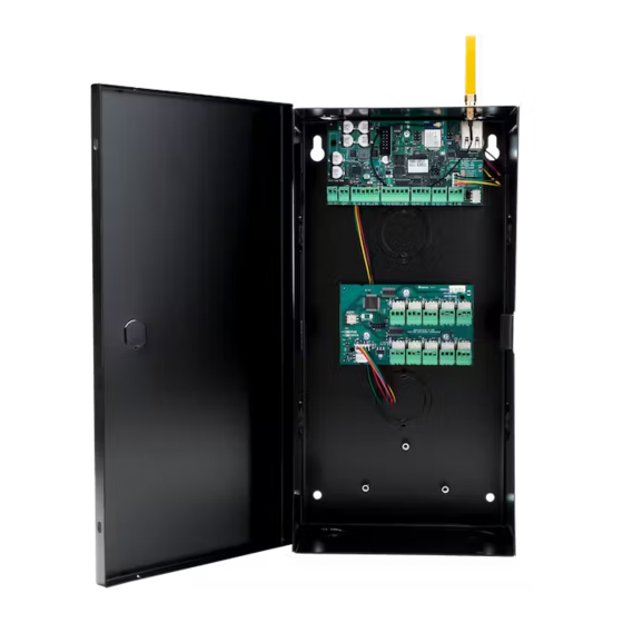
MOUNT THE PCB ONTO THE ENCLOSURE
The metal enclosure for the X1 Elevator Control Expansion Module (X1-ELEV-EXP)
comes with mounting holes for two additional X1 Elevator Control Module PCBs
(X1-ELEV-PCB). To mount the additional PCB, use the provided standoffs and
screw the PCB onto the 3 mounting holes.
SET THE ADDRESS
The X1 Elevator Control Module PCB (X1-ELEV-PCB) has a 1 through
9 addressable rotary dial that is factory defaulted to 1. Additional
elevator control modules need to be addressed in sequence.
LT-2466 21293 © 2021 Digital Monitoring Products, Inc.
This elevator control module can not be installed without being
0
Second X1 Elevator Module
Stando s (3)
X1 Elevator Expansion
Third X1 Elevator Module
0
Screws (3)
0
Advertisement
Table of Contents

Related Manuals for Digital Monitoring Products X1 Series


Summary of Contents for Digital Monitoring Products X1 Series
- Page 1 SET THE ADDRESS The X1 Elevator Control Module PCB (X1-ELEV-PCB) has a 1 through 9 addressable rotary dial that is factory defaulted to 1. Additional elevator control modules need to be addressed in sequence. LT-2466 21293 © 2021 Digital Monitoring Products, Inc.
- Page 2 X1 Elevator Controller Second X1 Elevator Module Third X1 Elevator Module First X1 Elevator Module 12 V Battery X1 Elevator Controller X1 Elevator Expansion X1 ELEVATOR CONTROL MODULE PCB ONLY | DIGITAL MONITORING PRODUCTS...
- Page 3 WIRE FOR FLOOR ACCESS The X1 Series Elevator Control Module provides 10 Form C (SPDT) 1 Amp relays for controlling access to 10 floors. The three relay terminals are labeled for normally open (NO) and normally closed (NC) operation. The center terminal is the common.
- Page 4 PROGRAM IN DEALER ADMIN™ Go to Dealer Admin (dealer.securecomwireless.com) to program the elevator control module. TEST THE CONTROLLER Make sure that the Reader LEDs are on and the elevator controller’s power LED is on. If connected to Wi-Fi, the Wi-Fi LED is on solid. If connected to network, the Network Port light is blinking.
Need help?
Do you have a question about the X1 Series and is the answer not in the manual?
Questions and answers