Table of Contents
Advertisement
Quick Links
X1 SERIES ELEVATOR
CONTROLLER
Quick Start Guide
PRE-INSTALLATION
Warning: This controller can not be installed without being in contact with the
elevator service company. This guide covers only what the elevator control
installer will be able to do.
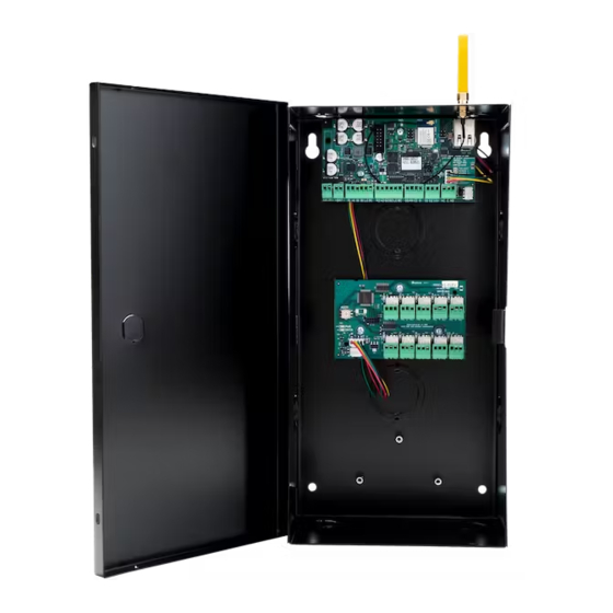
MOUNT THE CONTROLLER
The metal enclosure for the X1 Series Elevator Controller must be mounted directly to
a wall, backboard, or other flat surface in a secure, dry place to protect the controller
from damage. It is not necessary to remove the PCBs when installing the enclosure.
Address the rotary on the module to 1.
CONNECT A CARD READER
The X1 Series provides direct 12 VDC output to the reader on the RED terminal
connection.
The elevator service company supplies traveling cable wires for the reader. Document
which numbered conductors are connecting to which terminals on the elevator
controller.
Terminal Name
R1 & R2
W1 & W2
G1 & G2
B1 & B2
LC
BC
LT-2464 21293 © 2021 Digital Monitoring Products, Inc.
Wiegand Function
12V+
Data 1
Data 0
12V- (ground)
LED Control
Wiegand Buzzer Control
OSDP Function
DC +
B (485 +)
A (485 -)
DC -
N/A
N/A
Advertisement
Table of Contents

Related Manuals for Digital Monitoring Products X1 Series


Summary of Contents for Digital Monitoring Products X1 Series
- Page 1 Address the rotary on the module to 1. CONNECT A CARD READER The X1 Series provides direct 12 VDC output to the reader on the RED terminal connection. The elevator service company supplies traveling cable wires for the reader. Document which numbered conductors are connecting to which terminals on the elevator controller.
- Page 2 WIRE FOR FLOOR ACCESS The X1 Series Elevator Module provides 10 Form C (SPDT) 1 Amp relays for controlling access to 10 floors. The three relay terminals are labeled for normally open (NO) and normally closed (NC) operation. The center terminal is the common. See figures. These...
- Page 3 DETERMINE COMMUNICATION For more detailed information, follow the QR code at the end of this guide to see the full X1 Series Elevator Controller Installation and Programming Guide: LT-2463. Ethernet Connection Connect an Ethernet cable from the LAN/WAN connection to the X1 Ethernet port.
- Page 4 CONNECTION SETTINGS Wi-Fi LED If no network cable is attached, thirty seconds after power up the X1 broadcasts an SSID of DMPX1 followed by the controller’s serial number. No password is required to join the SSID. Configure Options Connect to the X1 SSID using a device capable of launching a browser (cell phone, laptop, etc.).
Need help?
Do you have a question about the X1 Series and is the answer not in the manual?
Questions and answers