Advertisement
Quick Links
Advertisement

Related Manuals for coesia FlexLink WL

Summary of Contents for coesia FlexLink WL
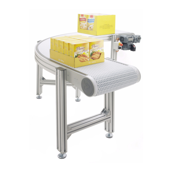
- Page 1 MAINTENANCE MANUAL MAINTENANCE MANUAL WL...
-
Page 2: Table Of Contents
Table of content 1. Troubleshooting ............3 2. Maintenance ............. 3 3. Conveyor assembly ........... 4 4. Slide rail and support rail ........... 5 4.1. Belts ................ 6 4.2. Roller Kit ..............9 FLX1006567-02©FlexLink 2021... -
Page 3: Troubleshooting
1. Troubleshooting Executed by skilled personnel Issue Cause Action Reference No rotation of Mechanically hindered Remove cause wheel Incorrectly connected Check sensors and or damaged electrical motor cables for dama- See Motor manual cables No indicator or red See Motor manual indicator on motor Troubleshooting executed with power on, must be executed only by skilled personnel which have taken necessary safety precautions. -
Page 4: Conveyor Assembly
3. Conveyor assembly Support profi les The beams are connected using the Connecting strips for beam. Note the different location of the support profi les due to belt wi- dth. See table below for placement of the support profi les. 4. -
Page 5: Slide Rail And Support Rail
Slide rail and support rail are standard FlexLink equipment and are described in the Mounting instruction; “Installation of plastic slide rail and support rail” (FLX1003231). FLEXLINK.COM The slide rails used in the WL conveyor system are mounted in three steps as shown below. XBCR 25 H WLCS 25x5 H XBCR 25 HB... -
Page 6: Belts
4.1. Belts The belts are delivered in one meter section to be manageable. They are mounted in the conveyor using the belt insertion section. The belt should be mounted with the front in the running direction. 1. Loosen the two screws and remove the cover on both sides. 2. - Page 7 3. Insert the belt and push it forward. 4. Assemble the belt section with the previous section; align the links on the two belts and insert the rod. 5. Press the rod into the belt until it “snaps” in place. FLX1006567-02©FlexLink 2021...
- Page 8 Continue inserting required number of belt sections. When the total number are installed and stretched the correct length should be checked. The belt should not be stretched neither be too long (compressed links behind the drive unit) Fitting the belt in the drive unit. It is important the belt fi ts into the cogs.
-
Page 9: Roller Kit
4.2. Roller Kit 1. Use the roller kit to relieve the belt from its own weight. The roller kit is mounted with a C-C of 400 mm all under the belt 84,6 4 3,2 2. The profi le needs to be mounted horizontally. 3. - Page 10 FLX1006567-02©FlexLink 2021...
- Page 11 info@fl exlink.com fl exlink.com...
- Page 12 FLX1006567-02©FlexLink 2021...
Need help?
Do you have a question about the FlexLink WL and is the answer not in the manual?
Questions and answers