Table of Contents
Advertisement
Available languages
Available languages
Quick Links
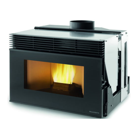
INSERIMENTI A70/AC70
MANUALE DI INSTALLAZIONE, USO E MANUTENZIONE
Il presente manuale è parte integrante del prodotto.
Si raccomanda di leggere attentamente le istruzioni prima
dell'installazione, manutenzione o utilizzo del prodotto.
Istruzioni originali
INSTALLATION, USE AND MAINTENANCE MANUAL
This manual is an integral part of the product.
Read the instructions carefully before installing, servicing or
operating the product.
Translation of the original instructions
MANUEL D'INSTALLATION, D'UTILISATION ET DE MAINTENANCE
Le présent manuel fait partie intégrante du produit.
Il est conseillé de lire attentivement les consignes avant
l'installation, l'entretien ou l'utilisation du produit.
Traduction des instructions originales
INSTALLATIONS-, BEDIENUNGS- UND WARTUNGSHANDBUCH
Die vorliegende Anleitung ist fester Bestandteil des Produkts.
Vor der Installation, Wartung und Verwendung die Anleitugen
stets aufmerksam durchlesen.
Übersetzung der Original-Bedienungsanleitung
MANUAL DE INSTALACIÓN, USO Y MANTENIMIENTO
Este manual es parte integrante del producto.
Se recomienda leer detenidamente las instrucciones antes de la
instalación, el mantenimiento y el uso del producto.
Traducción de las instrucciones originales
Advertisement
Chapters
Table of Contents

Related Manuals for Palazzetti INSERIMENTI A70


Summary of Contents for Palazzetti INSERIMENTI A70
- Page 1 INSERIMENTI A70/AC70 MANUALE DI INSTALLAZIONE, USO E MANUTENZIONE Il presente manuale è parte integrante del prodotto. Si raccomanda di leggere attentamente le istruzioni prima dell’installazione, manutenzione o utilizzo del prodotto. Istruzioni originali INSTALLATION, USE AND MAINTENANCE MANUAL This manual is an integral part of the product.
- Page 2 Gentile cliente, desideriamo innanzitutto ringraziarLa per la preferenza che ha voluto accordarci acquistando il nostro prodotto e ci congratuliamo con Lei per la scelta. Per consentirLe di utilizzare al meglio il suo prodotto, la invitiamo a seguire attentamente quanto descritto nel presente manuale.
- Page 3 ITALIANO ENGLISH FRANÇAIS DEUTSCH ESPAÑOL INDICE Utente e Installatore Installatore 1 PREMESSA GENERALE Simbologia Destinazione d’uso Scopo e contenuto del manuale Conservazione del manuale Aggiornamento del manuale Generalità Conformità Responsabilità del costruttore Assistenza tecnica e manutenzione 1.10 Parti di ricambio 1.11 Targhetta matricola 1.12 Consegna dell’apparecchio...
- Page 4 5 MOVIMENTAZIONE E TRASPORTO Trasporto 6 PREPARAZIONE DEL LUOGO DI INSTALLAZIONE Considerazioni generali 6.2 Precauzioni per la sicurezza 6.3 Luogo d’installazione 6.4 Aria comburente 6.5 Raccordo fumi 6.6 Scarico a tetto mediante camino tradizionale 7 INSTALLAZIONE Considerazioni generali 7.2 Configurazioni installative A70/AC70 7.3 Schema di montaggio 7.4 Collegamento mandata aria calda 7.5 Realizzazione fori tecnici sul rivestimento...
- Page 5 Palazzetti. Il manuale d’installazione è parte integrante Palazzetti si riserva il diritto di modificare spe- dell’apparecchio. cifiche e caratteristiche tecniche e/o funzionali Deterioramento o smarrimento del prodotto in qualsiasi momento senza darne preavviso.
- Page 6 La responsabilità delle opere eseguite per l’in- zate e/o regolamenti: stallazione dell'apparecchio non può essere con- EMCD: siderata a carico della Palazzetti; essa è e rimane - EN 55014-1:2017 a carico dell’installatore, al quale è demandata - EN 61000-3-2:2015 l’esecuzione delle verifiche relative alla canna fumaria, alla presa d’aria e alla correttezza delle...
- Page 7 L’apparecchio viene consegnato perfettamente imballato e fissato ad una pedana in legno che Palazzetti mette a disposizione una fitta rete di ne permette la movimentazione mediante car- centri di assistenza con tecnici specializzati, for- relli elevatori e/o altri mezzi.
- Page 8 AVVERTENZE PER LA Verificare che le predisposizioni SICUREZZA della canna fumaria e della presa d’aria siano conformi al tipo d’installazione. Avvertenze per l’installatore Osservare le prescrizioni indicate nel Non effettuare collegamenti elettrici presente manuale. volanti con cavi provvisori o non isolati. Verificare che la messa a terra dell’im- Le istruzioni di montaggio e pianto elettrico sia efficiente.
- Page 9 ITALIANO ENGLISH FRANÇAIS DEUTSCH ESPAÑOL 2.2 Avvertenze per il personale 2.3 Avvertenze per l'utilizzatore tecnico addetto alla manutenzione Per il corretto uso del prodotto e delle Le operazioni di manutenzione devono apparecchiature elettroniche ad essa essere eseguite solo da personale auto- collegate e per prevenire incidenti si devono sempre osservare le indicazioni rizzato e qualificato.
- Page 10 alla comprensione dei pericoli ad esso do la connessione elettrica di rete. inerenti. I bambini non devono giocare Non appoggiarsi sulla porta aperta, con l'apparecchio. La pulizia destinata potrebbe compromettere la stabilita ad essere effettuata dall'utilizzatore dell'apparecchio. non deve essere effettuata da bambini senza sorveglianza.
- Page 11 ITALIANO ENGLISH FRANÇAIS DEUTSCH ESPAÑOL Utilizzare esclusivamente il combu- È vietato far funzionare l'appa- stibile raccomandato dal produttore. recchio con la porta aperta. Il prodotto non deve essere utilizzato come inceneritore. È vietato utilizzare l'apparecchio se il È vietato utilizzare benzina, combustibi- vetro o le guarnizioni della porta sono le per lampade, kerosene, accendifuoco danneggiati.
- Page 12 CARATTERISTICHE DEL locale attiguo purché sia a temperatura e umidità adeguate e a una distanza di sicurezza (almeno COMBUSTIBILE un metro) da fonti di calore. II pellet umido e/o freddo (5 °C) riduce la poten- Caratteristiche del combustibile zialità termica del combustibile ed obbliga ad effettuare maggiore manutenzione di pulizia del II pellet (Fig.
- Page 13 ITALIANO ENGLISH FRANÇAIS DEUTSCH ESPAÑOL CONOSCERE IL PRODOTTO 4.1 Descrizione INSERIMENTO AC70 (CANALIZZATO) Fig. 3 Tubo uscita fumi Serbatoio pellet Sistema di caricamento Maniglia di apertura Termostato a riarmo manuale Porta Scheda elettronica Gancio di chiusura Sonda ambiente Vano cenere Ventilatore ambiente Braciere Microinterruttore...
- Page 14 INSERIMENTO A70 (FRONTALE) Fig. 4 Tubo uscita fumi Serbatoio pellet Sistema di caricamento Maniglia di apertura Termostato a riarmo manuale Porta Scheda elettronica Gancio di chiusura Sonda ambiente Vano cenere Ventilatore ambiente Braciere Microinterruttore Camera di combustione Cavo di alimentazione Ventilatore fumi 004778740 - 14/06/2021...
- Page 15 ITALIANO ENGLISH FRANÇAIS DEUTSCH ESPAÑOL 4.2 Dimensioni INSERIMENTO A70 (FRONTALE) Ø 74,5 258,5 Dimensioni in mm Fig. 5 004778740 - 14/06/2021...
- Page 16 INSERIMENTO AC70 (CANALIZZATO) 627,5 Ø 192 74,5 258,5 Ø138,5 Dimensioni in mm Fig. 6 004778740 - 14/06/2021...
- Page 17 ITALIANO ENGLISH FRANÇAIS DEUTSCH ESPAÑOL 4.3 Caratteristiche tecniche AC70 A70/AC70 kcal/h 2493 7739 2493 7739 Potenza termica globale (resa) Rendimento 94,5 90,7 94,5 90,7 Temperatura fumi °C 64,9 124,4 64,9 124,4 Portata fumi 4,13 4,13 Consumo orario di combustibile kg/h 0,643 2,05 0,643...
- Page 18 4.4 Targhetta matricola Palazzetti Lelio S.p.A. - via Roveredo 103 - 33080 Porcia (PN) Combustibile Pellet Potenza termica max introdotta PImax Potenza termica min introdotta PImin Potenza termica nominale Pmax Potenza termica ridotta Pmin Rendimento alla potenza nominale EFFmax Rendimento alla potenza ridotta...
- Page 19 ITALIANO ENGLISH FRANÇAIS DEUTSCH ESPAÑOL 4.5 Schema elettrico A70/AC70 t° t° t° UI / ∆ +16V I03 GND CN12 CN10 L ~220÷240 N exaust Air L Air R NOTE: Phase protection, added by customer. Do not change polarity! 004725190 - 21/12/2020 ~220÷240 Vac Fig.
- Page 20 MOVIMENTAZIONE E TRASPORTO L'apparecchio viene consegnato completo di tutte le parti previste. Fare attenzione alla tendenza allo sbilanciamen- to dell'apparecchio. II baricentro dell'apparecchio è spostato verso la parte anteriore. Tenere ben presente quanto sopra anche du- rante lo spostamento dell'apparecchio sul sup- porto di trasporto.
- Page 21 ITALIANO ENGLISH FRANÇAIS DEUTSCH ESPAÑOL Trasporto Accertarsi che il carrello sollevatore abbia una portata superiore al peso dell’apparecchiatura da sollevare. Al manovratore dei mezzi di sollevamen- to spetterà tutta la responsabilità del sollevamento dei carichi. Porre particolare attenzione a proteg- gere adeguatamente i pavimenti in legno o parquet per evitare che il peso dell’apparecchio possa rovinarli duran-...
- Page 22 PREPARAZIONE DEL LUOGO DI INSTALLAZIONE Considerazioni generali Nei paragrafi successivi sono riportate alcune indicazioni da rispettare per ottenere il massimo rendimento del prodotto acquistato e il funzio- namento in sicurezza. Le seguenti indicazioni rimangono comunque subordinate al rispetto di eventuali leggi e normative nazionali, regionali e comunali vigenti nel paese dove avviene l’instal- lazione dell'apparecchio.
- Page 23 ITALIANO ENGLISH FRANÇAIS DEUTSCH ESPAÑOL 6.4 Aria comburente L'apparecchio, durante il suo funzionamento, necessita di aria comburente. L'afflusso di aria comburente può essere ottenu- to attraverso una presa d’aria esterna al locale stesso (PA = Presa d'Aria). Prelievo dell'aria comburente in ambiente Realizzare la presa d'aria sulla parete (Fig.
- Page 24 Max 4 mt. Fig. 18 Fig. 19 Se la parete posteriore dell'apparecchio è una È vietato il prelievo di aria comburente da garage, parete esterna, realizzare un foro per l'aspira- magazzini di materiale combustibile o locali con zione dell'aria comburente ad una altezza dal attività...
- Page 25 ITALIANO ENGLISH FRANÇAIS DEUTSCH ESPAÑOL 6.5 Raccordo fumi L'apparecchio funziona con la camera di combu- stione in depressione è pertanto indispensabile assicurarsi che lo scarico dei fumi sia a tenuta (operazione a carico dell'installatore). L'apparecchio deve essere collegato ad un pro- prio condotto di evacuazione fumi non condiviso, e idoneo ad assicurare un'adeguata dispersione in atmosfera dei prodotti della combustione,...
- Page 26 6.6 Scarico a tetto mediante camino In caso di camino di sezione maggiore tradizionale è necessario “intubare” il camino con una tubazione in acciaio (con diametro Il camino per lo scarico dei fumi deve essere rea- in funzione del percorso) opportuna- lizzato da personale qualificato in osservanza alle mente isolato (Fig.
- Page 27 ITALIANO ENGLISH FRANÇAIS DEUTSCH ESPAÑOL INSTALLAZIONE • Riposizionare la macchina nelle guide di scor- rimento Considerazioni generali Nei paragrafi successivi sono riportate alcune indicazioni da rispettare per ottenere il massimo rendimento dal prodotto acquistato. Le seguenti indicazioni rimangono comunque subordinate rispetto di eventuali leggi e normative nazio- nali, regionali e comunali vigenti nel...
- Page 28 7.3 Schema di montaggio • Aprire la porta, inserire la brugola (1) nella sede di sblocco fermo; ruotare in senso orario la leva A) Per una corretta installazione la conduttura di chiusura in posizione (2) per bloccare le gui- fumi tra caminetto e canna fumaria va fatta a tenuta stagna sigillando tutti i giunti di unione.
- Page 29 ITALIANO ENGLISH FRANÇAIS DEUTSCH ESPAÑOL 7.3.1 Inserimento sonda ambiente La sonda deve essere installata in prossimità dei fori di aspirazione laterale o frontale della base del rivestimento. Incollare il filo della sonda in corrispondenza delle prese d’aria Fig. 32 Le bocchette vanno fissate sulla cappa o su una parete ad una altezza di almeno 1,8 ÷...
- Page 30 Doppio condotto 7.5 Realizzazione fori tecnici sul rivestimento Il rivestimento deve essere fatto solo da persona- le qualificato. Sul rivestimento e sulla cappa devono essere eseguiti i fori tecnici per: A) alloggiamento display; B) le bocchette di aerazione; C) lo sfogo di calore in cappa; D) l’aerazione del rivestimento sul basamento;...
- Page 31 ITALIANO ENGLISH FRANÇAIS DEUTSCH ESPAÑOL 7.6 Collegamento elettrico 7.6.1 Installazione del pannello di controllo Il pannello di controllo dell'apparecchio può È sufficiente collegare l'apparecchio all'impianto essere applicato a parete. elettrico attraverso la spina in dotazione (Fig. 36). II collegamento elettrico (spina) deve essere facilmente accessibile anche dopo l'installazione dell'apparecchio.
- Page 32 PRIMA ACCENSIONE AC70 La prima accensione deve essere esegui- ta dall'installatore. Carico pellet Il pellet va caricato da uno sportello da preve- dere nella cappa del rivestimento e collegato all'apparecchio attraverso gli appositi accessori (optional), seguendo attentamente le istruzioni di montaggio Non utilizzare il sistema di estrazione dell'apparecchio come mezzo per carica- re il serbatoio di pellet.
- Page 33 ITALIANO ENGLISH FRANÇAIS DEUTSCH ESPAÑOL 8.2 Primo avvio Durante la prima accensione dell'appa- recchio mantenere i locali ben arieggiati, in quanto si possono generare sgradevo- li odori o fumi causati dall'evaporazione o dall'essiccamento di alcuni materiali utilizzati. Tale fenomeno andrà via via a scomparire.
- Page 34 MANUTENZIONE Le operazioni di manutenzione devono essere effettuate da parte di un centro di assistenza tecnico autorizzato. Prima di effettuare qualsiasi operazione di manutenzione adottare le seguenti precauzioni: • Assicurarsi che tutte le parti dell'apparecchio siano fredde. • Accertarsi che le ceneri siano completamente spente. •...
- Page 35 ITALIANO ENGLISH FRANÇAIS DEUTSCH ESPAÑOL 9.3 Programma di pulizia e manutenzione 9.3.1 Manutenzione ordinaria (Utente) OGNI OGNI SETTIMANA 1 MESE ACCENSIONE Braciere (Fig. 42) Cassetto/Vano cenere (Fig. 44 - Fig. 45) Vetro (Fig. 46) Collettore fumi 9.3.2 Manutenzione straordinaria (Centro di assistenza tecnico abilitato) 1 ANNO (*) Guarnizioni porta e braciere Condotto di evacuazione fumi...
- Page 36 9.4 Manutenzione ordinaria Se necessario, estrarre la griglia cenere e svuotarlo, avendo cura di ripulire il vano che lo contiene da eventuali residui (Fig. 44). 9.4.1 Pulizia interna del focolare Quotidianamente oppure prima di ogni accensio- L’uso di un aspiracenere può semplifi- ne è...
- Page 37 ITALIANO ENGLISH FRANÇAIS DEUTSCH ESPAÑOL Non pulire il vetro durante il funzionamento • Spingere la macchina fino in fondo alle guide. dell'apparecchio e non utilizzare spugne abrasive. • Utilizzare un aspiracenere per rimuovere i resi- dui all'interno del Tee. ATTENZIONE: non utilizzare solventi, acidi o detersivi, detergenti liquidi o prodotti aggressivi.
- Page 38 In caso di mancata o inadeguata pulizia l'appa- recchio può avere problemi di funzionalità quali: • Cattiva combustione; • Annerimento del vetro; • Intasamento del braciere con accumulo di ce- neri e pellet; • Deposito di ceneri ed eccessive incrostazioni sullo scambiatore con conseguente scarso ren- dimento 9.5.4 Manutenzione dell'apparecchio...
- Page 39 ITALIANO ENGLISH FRANÇAIS DEUTSCH ESPAÑOL • Rimuovere i refrattari dal vano fuoco e aspirare • Rimuovere i supporti refrattari laterali la cenere residua. Fig. 54 Fig. 56 • Rimuovere i tappi caldaia superiori ed aspirare • Rimuovere i tappi vano ventilatore fumi la cenere residua.
- Page 40 • Aspirare la cenere residua Fig. 58 • Rimontare tutti i componenti in ordine contra- • Verificare lo stato e la buona tenuta di tutte le guarnizioni • Verificare lo stato e la pulizia di tutti i compo- nenti interni •...
- Page 41 ITALIANO ENGLISH FRANÇAIS DEUTSCH ESPAÑOL 10 DEMOLIZIONE E SMALTIMENTO La responsabilità per eventuali danni a persone La demolizione e lo smaltimento dell'apparec- ed animali ricade sempre sul proprietario. All’atto chio sono ad esclusivo carico e responsabilità del della demolizione la marcatura CE, il presente proprietario che dovrà...
-
Page 42: Table Of Contents
CONTENTS User and Installer Installer 1 GENERAL INTRODUCTION Symbols Intended use Purpose and content of the manual Preservation of the manual Update of this manual Overview Compliance Responsibility of the manufacturer Technical assistance and maintenance 1.10 Spare parts 1.11 Serial plate 1.12 Delivery of the appliance 2 SAFETY WARNING Warnings for the installer... - Page 43 ITALIANO ENGLISH FRANÇAIS DEUTSCH ESPAÑOL 5 HANDLING AND TRANSPORTATION Transportation 6 PREPARATION OF THE INSTALLATION SITE General considerations 6.2 Safety Precautions 6.3 Place of installation 6.4 Combustion air 6.5 Flue gas fitting 6.6 Roof exhaust with traditional fireplace 7 INSTALLATION General considerations 7.2 Installation configurations A70 AC70 7.3 Assembly diagram...
-
Page 44: General Introduction
Palazzetti specialised personnel. The installation manual is an integral part of the appliance. Palazzetti reserves the right to change specifi- cations and technical and/or functional charac- Deterioration or loss teristics of the product at any time without prior If needed, request an additional copy from notice. -
Page 45: Compliance
Responsibility for the works carried out for the in- stallation of the appliance cannot be considered The following harmonised standards and/or reg- to be taken on by Palazzetti; it is and remains the ulations have been applied: responsibility of the installer, who is responsible... -
Page 46: Technical Assistance And Maintenance
1.12 Delivery of the appliance maintenance The appliance is delivered perfectly packaged and fixed to a wooden platform which allows Palazzetti has a dense network of service centres handling it using fork lift trucks and/or other with specialised, trained and skilled technicians. means. -
Page 47: Safety Warning
ITALIANO ENGLISH FRANÇAIS DEUTSCH ESPAÑOL SAFETY WARNING Do not carry out on-the-fly electrical connections with temporary or uninsu- lated cables. Warnings for the installer Check that the earthing of the electri- Observe the prescriptions contained in cal system is efficient. this manual. -
Page 48: Warnings For Technical Maintenance Personnel
2.2 Warnings for technical 2.3 Warnings for users maintenance personnel To ensure correct use of the product Maintenance operations must be car- and electronic appliances connected ried out only by authorised and quali- thereto and to prevent accidents, it is important to always follow the instruc- fied personnel. - Page 49 ITALIANO ENGLISH FRANÇAIS DEUTSCH ESPAÑOL responsible must not be carried out by Do not use the appliance as an anchor unsupervised children. support of any kind. Before performing any type of opera- It is prohibited to use the product as a tion, the user or whoever is operating ladder or support structure.
- Page 50 Any type of unauthorised handling or operation. replacement with non-original spare It is prohibited to insert other types parts shall place the safety of the opera- of fuels in the tank other than wood tor at risk and relieve the manufacturer pellets.
-
Page 51: Fuel Characteristics
ITALIANO ENGLISH FRANÇAIS DEUTSCH ESPAÑOL FUEL CHARACTERISTICS (at least one meter) away from heat sources. Wet and/or cold pellets (5 °C) reduce the ther- mal potential of the fuel resulting in the need Fuel characteristics for more cleaning maintenance of the burn pot (unburned material) and of the fire box. -
Page 52: Becoming Familiar With The Product
BECOMING FAMILIAR WITH THE PRODUCT 4.1 Description INSERT AC70 (CHANNELLED) Fig. 3 Smoke outlet pipe Pellet hopper Loading system Opening handle Manual reset thermostat Door Faulty Closing hook Room sensor Ash compartment Room fan Burn pot Microswitch Combustion chamber Power cable Flue gas fan 004778740 - 14/06/2021... - Page 53 ITALIANO ENGLISH FRANÇAIS DEUTSCH ESPAÑOL INSERT A70 (FRONT) Fig. 4 Smoke outlet pipe Pellet hopper Loading system Opening handle Manual reset thermostat Door Faulty Closing hook Room sensor Ash compartment Room fan Burn pot Microswitch Combustion chamber Power cable Flue gas fan 004778740 - 14/06/2021...
-
Page 54: Dimensions
4.2 Dimensions INSERT A70 (FRONT) Ø 74,5 258,5 Dimensions in mm Fig. 5 004778740 - 14/06/2021... - Page 55 ITALIANO ENGLISH FRANÇAIS DEUTSCH ESPAÑOL INSERT AC70 (CHANNELLED) 627,5 Ø 192 74,5 258,5 Ø138,5 Dimensions in mm Fig. 6 004778740 - 14/06/2021...
-
Page 56: Technical Features
4.3 Technical features AC70 A70 AC70 kcal/h 2493 7739 2493 7739 Overall thermal power (output) Yield 94.5 90.7 94.5 90.7 Flue gas temperature °C 64.9 124.4 64.9 124.4 Flue gas flow rate 4.13 4.13 Hourly fuel consumption kg/h 0.643 2.05 0.643 2.05 CO emissions (at 13% of O2) -
Page 57: Serial Plate
ITALIANO ENGLISH FRANÇAIS DEUTSCH ESPAÑOL 4.4 Serial plate Palazzetti Lelio S.p.A. - via Roveredo 103 - 33080 Porcia (PN) Combustibile Pellet Potenza termica max introdotta PImax Potenza termica min introdotta PImin Potenza termica nominale Pmax Potenza termica ridotta Pmin Rendimento alla potenza nominale... -
Page 58: Wiring Diagram
4.5 Wiring diagram A70 AC70 t° t° t° UI / ∆ +16V I03 GND CN12 CN10 L ~220÷240 N exaust Air L Air R NOTE: Phase protection, added by customer. Do not change polarity! 004725190 - 21/12/2020 ~220÷240 Vac Fig. 8 Hall sensor Loading dispenser External thermostat... -
Page 59: Handling And Transportation
ITALIANO ENGLISH FRANÇAIS DEUTSCH ESPAÑOL HANDLING AND TRANSPORTATION The appliance is delivered complete with all the parts required. Pay attention to the tendency for the appliance to become unbalanced. The centre of gravity of the appliance is carried towards the front. Bear in mind the above also when moving the appliance on the transport stand. -
Page 60: Transportation
Transportation Make sure that the lifting carriage has a payload higher than the weight of the appliance to be lifted. The full responsi- bility of the lifting of loads lies with the person handling the lifting equipment. Ensure wood or timber floors are prop- erly protected in order to prevent the weight of the appliance from damag- ing them during movement. -
Page 61: Preparation Of The Installation Site
ITALIANO ENGLISH FRANÇAIS DEUTSCH ESPAÑOL PREPARATION OF THE INSTALLATION SITE General considerations The following paragraphs contain some guide- lines to be followed to obtain the maximum efficiency of the product purchased and to ensure safe operation. The following indications are however subject to compliance with any possible national, regional and municipal laws and regulations in force in the country where the appliance is installed. -
Page 62: Combustion Air
6.4 Combustion air The appliance, during its operation, requires combustion air. The inflow of combustion air can be obtained through an air intake outside the room itself (PA = Air Intake). Extraction of combustion air in the room Create the air intake on the wall (Fig. 17 - PA=Air Intake), and leave the appliance to withdraw the room air, making sure to connect the section of corrugated pipe on the air inlet pipe, if supplied,... - Page 63 ITALIANO ENGLISH FRANÇAIS DEUTSCH ESPAÑOL Max 4 mt. Fig. 18 Fig. 19 If the rear wall of the appliance is an external wall, It is forbidden to take combustion air from ga- make a hole for the intake of combustion air at a rages, warehouses of combustible material or height of about 20-30 cm from the ground, re- places with activities at risk of fire.
-
Page 64: Flue Gas Fitting
6.5 Flue gas fitting The appliance works with the combustion cham- ber at negative pressure. It is therefore essential to make sure that the flue gas evacuation is airtight (this is the responsibility of the installer). The appliance must be connected to its own flue gas duct, not shared, and which is suitable for ensuring adequate dispersion of the combustion products into the atmosphere, in accordance... -
Page 65: Roof Exhaust With Traditional Fireplace
ITALIANO ENGLISH FRANÇAIS DEUTSCH ESPAÑOL 6.6 Roof exhaust with traditional If the chimney has a larger section, it fireplace must be “intubated” with a suitably in- sulated steel pipe (with diameter suita- The flue for flue gas discharge must be carried ble for the route) (Fig. -
Page 66: Installation
INSTALLATION • Reposition the machine in the sliding guides General considerations In the following paragraphs some indications are provided to be respected in order to obtain the maximum performance from the purchased product. The following indications are how- ever subject to compliance with any possible national, regional and mu- nicipal laws and regulations in force in the country where the appliance is... -
Page 67: Assembly Diagram
ITALIANO ENGLISH FRANÇAIS DEUTSCH ESPAÑOL 7.3 Assembly diagram • Open the door, insert the Allen key (1) in the stop release seat; turn the locking lever clock- A) For correct installation, all the joints of the wise to position (2) to lock the guides smoke ducting between the fireplace and the flue must be sealed. -
Page 68: Hot Air Delivery Connection
7.3.1 Insertion of room sensor The sensor must be installed near the side or front suction holes of the cladding base. Glue the probe wire in correspondence with the air intakes Fig. 32 The vents are fixed on the hood or on a wall at a height of at least 1.8 ÷... -
Page 69: Making Technical Holes On The Cladding
ITALIANO ENGLISH FRANÇAIS DEUTSCH ESPAÑOL Double duct 7.5 Making technical holes on the cladding The cladding must only be done by qualified personnel. Technical holes must be made on the cladding and on the hood for: A) the display housing; B) the air vents;... -
Page 70: Electrical Connection
7.6 Electrical connection 7.6.1 Installation of the control panel The control panel of the appliance can be applied Simply connect the appliance to the electrical to the wall. system using the supplied plug (Fig. 36). The electrical connection (plug) must be easily accessible after appliance installation as well. -
Page 71: First Ignition
ITALIANO ENGLISH FRANÇAIS DEUTSCH ESPAÑOL FIRST IGNITION AC70 The first ignition must be carried out by the installer. Pellet loading The pellets must be loaded from a door which must be provided in the hood of the cladding and connected to the appliance through the appropriate accessories (optional), carefully fol- lowing the assembly instructions Do not use the extraction system of the... -
Page 72: First Start Up
8.2 First start up During the first ignition of the appli- ance, make sure the rooms are prop- erly ventilated as unpleasant odours or fumes may be generated due to the evaporation or drying of certain mate- rials used. This phenomenon will grad- ually disappear. -
Page 73: Maintenance
ITALIANO ENGLISH FRANÇAIS DEUTSCH ESPAÑOL MAINTENANCE Maintenance operations must be performed by an authorised technical assistance centre. Before performing any maintenance operation, take the following precautions: • Ensure that all appliance parts are cold. • Make sure that the ashes are completely extinguished. •... -
Page 74: Cleaning And Maintenance Program
9.3 Cleaning and maintenance program 9.3.1 Ordinary maintenance (User) EACH IGNITION EVERY WEEK 1 MONTH Burn pot (Fig. 42) Ash drawer/compartment (Fig. 44 - Fig. 45) Glass (Fig. 46) Flue manifold 9.3.2 Extraordinary maintenance (authorised technical assistance centre) 1 YEAR (*) Door and burn pot seals Smoke exhaust duct Fans... -
Page 75: Ordinary Maintenance
ITALIANO ENGLISH FRANÇAIS DEUTSCH ESPAÑOL 9.4 Ordinary maintenance If necessary, remove the ash grate and empty it, taking care to clean any residue that may be contained in the compartment (Fig. 44). 9.4.1 Cleaning the inside of the firebox Daily or before each ignition, it is necessary to Using an ash vacuum can simplify the check that the burn pot is clean to ensure the cleaning operations... -
Page 76: Extraordinary Maintenance
Do not clean the glass while the appliance is • Push the machine all the way to the end posi- operating and do not use abrasive sponges. tion of the guides. • Use an ash vacuum cleaner to remove debris ATTENTION: do not use solvents, acids, inside the Tee. - Page 77 ITALIANO ENGLISH FRANÇAIS DEUTSCH ESPAÑOL In the event of failure to clean or inadequate cleaning the appliance may have operating problems including: • Poor combustion; • Blackening of the glass; • Blockage of the burn pot with accumulation of ash and pellets; •...
- Page 78 • Remove the refractory panels from the fire • Remove the lateral refractory supports compartment and vacuum the residual ash. Fig. 54 Fig. 56 • Remove the upper boiler caps and vacuum the • Remove the flue gas fan compartment caps residual ash.
- Page 79 ITALIANO ENGLISH FRANÇAIS DEUTSCH ESPAÑOL • Vacuum the residual ash Fig. 58 • Re-assemble all the components in reverse or- • Check the condition and tightness of all the seals • Check the condition of all internal components and make sure they are clean •...
-
Page 80: Demolition And Disposal
10 DEMOLITION AND DISPOSAL Any liability for damage to people and animals The demolition and disposal of the appliance are always falls on the owner. Upon demolition, the the sole liability and responsibility of the owner EC marking, this manual and other documents who must act in compliance with the laws in relating to this appliance must be destroyed. - Page 81 ITALIANO ENGLISH FRANÇAIS DEUTSCH ESPAÑOL TABLE DES MATIÈRES Utilisateur et Installateur Installateur 1 INTRODUCTION Symboles utilisés Destination d’emploi Objet et contenu du manuel Conservation du manuel Mise à jour du manuel Généralités Conformité Responsabilité du fabricant Assistance technique et entretien 1.10 Pièces détachées 1.11 Plaque signalétique...
- Page 82 5 MANUTENTION ET TRANSPORT Transport 6 PRÉPARATION DU LIEU D’INSTALLATION Considérations générales 6.2 Précautions pour la sécurité 6.3 Lieu d’installation 6.4 Air de combustion 6.5 Raccord fumée 6.6 Évacuation sur le toit à travers un conduit de cheminée traditionnel 104 7 INSTALLATION Considérations générales 7.2 Configurations d’installation A70/AC70...
-
Page 83: Introduction
Le manuel d’installation fait partie intégrante de spécialisé Palazzetti. l’appareil. Palazzetti se réserve le droit de modifier les spé- Perte ou détérioration cifications et les caractéristiques techniques et/ ou fonctionnelles du produit à tout moment sans Si nécessaire, demander un autre exemplaire à... -
Page 84: Conformité
La responsabilité des travaux exécutés pour l’ins- tallation de l’appareil ne peut pas être considérée - EN 55014-1:2017 à la charge de la société Palazzetti ; en effet, celle- - EN 61000-3-2:2015 ci est et reste à la charge de l’installateur qui est - EN 61000-3-3:2014 /EC:2016 tenu d’effectuer les contrôles relatifs au conduit... -
Page 85: Assistance Technique Et Entretien
DEUTSCH ESPAÑOL Assistance technique et entretien 1.12 Livraison de l’appareil Palazzetti met à disposition un réseau dense de L'appareil est livré parfaitement emballé et fixé centres d’assistance avec des techniciens spécia- à une palette en fois permettant de le déplacer lisés, formés et préparés. -
Page 86: Avertissements Pour La Sécurité
AVERTISSEMENTS POUR Vérifier que les prédispositions LA SÉCURITÉ du conduit de fumée et de l'ar- rivée d'air soient conformes au type d'installation. Avertissements pour l'installateur Respecter les consignes indiquées Ne pas effectuer de branchements dans le présent manuel. électriques volants avec des câbles provisoires ou non isolés. -
Page 87: Avertissements Pour Les Techniciens Préposés À La Maintenance
ITALIANO ENGLISH FRANÇAIS DEUTSCH ESPAÑOL 2.2 Avertissements pour les 2.3 Avertissements pour l’utilisateur techniciens préposés à la Pour une utilisation correcte du produit maintenance et des équipements électroniques qui y sont connectés et pour prévenir les acci- Les opérations de maintenance doivent dents, les instructions données dans ce être effectuées exclusivement par un manuel doivent toujours être respectées. - Page 88 relatives à l'usage sûr de l'appareil et à la chant la connexion électrique de secteur. compréhension des dangers afférents. Ne pas s’appuyer sur la porte ouverte, Les enfants ne doivent pas jouer avec cela pourrait compromettre la stabilité l’appareil. Le nettoyage qui doit être ef- de l’appareil.
- Page 89 ITALIANO ENGLISH FRANÇAIS DEUTSCH ESPAÑOL pénale. un entretien incorrect peut entraîner un risque sérieux d'explosion dans la Il est interdit de faire fonctionner chambre de combustion. l'appareil avec la porte ouverte. Utiliser uniquement le combustible recommandé par le fabricant. Le pro- Il est interdit d'utiliser l'appareil si les duit ne doit pas être utilisé...
-
Page 90: Caractéristiques Du Combustible Caractéristiques Du Combustible
CARACTÉRISTIQUES DU pièce voisine à condition que la température et l’humidité soient adéquates et à une distance de COMBUSTIBLE sécurité (au moins 1 mètre) de toute source de chaleur. Caractéristiques du combustible Les granulés humides et/ou froids (5 °C) ré- duisent la puissance thermique du combustible Les granulés de bois (Fig. -
Page 91: Connaître Le Produit
ITALIANO ENGLISH FRANÇAIS DEUTSCH ESPAÑOL CONNAÎTRE LE PRODUIT 4.1 Description INSERT AC70 (CANALISÉ) Fig. 3 Tube d’évacuation des fumées Réservoir granulés Système de chargement Poignée d’ouverture Thermostat à réarmement manuel Porte Carte électronique Crochet de fermeture Sonde ambiante Compartiment à cendres Ventilateur ambiant Brasier Microrupteur... - Page 92 INSERT A70 (FRONTAL) Fig. 4 Tube d’évacuation des fumées Réservoir granulés Système de chargement Poignée d’ouverture Thermostat à réarmement manuel Porte Carte électronique Crochet de fermeture Sonde ambiante Compartiment à cendres Ventilateur ambiant Brasier Microrupteur Chambre de combustion Câble d’alimentation Ventilateur fumées 004778740 - 14/06/2021...
-
Page 93: Dimensions
ITALIANO ENGLISH FRANÇAIS DEUTSCH ESPAÑOL 4.2 Dimensions INSERT A70 (FRONTAL) Ø 74,5 258,5 Dimensions en mm Fig. 5 004778740 - 14/06/2021... - Page 94 INSERT AC70 (CANALISÉ) 627,5 Ø 192 74,5 258,5 Ø138,5 Dimensions en mm Fig. 6 004778740 - 14/06/2021...
-
Page 95: Caractéristiques Techniques
ITALIANO ENGLISH FRANÇAIS DEUTSCH ESPAÑOL 4.3 Caractéristiques techniques AC70 A70/AC70 kcal/h 2493 7739 2493 7739 Puissance thermique globale (délivrée) Rendement 94,5 90,7 94,5 90,7 Température des fumées °C 64,9 124,4 64,9 124,4 Débit des fumées 4,13 4,13 Consommation horaire de combustible kg/h 0,643 2,05... -
Page 96: Plaque Signalétique
4.4 Plaque signalétique Palazzetti Lelio S.p.A. - via Roveredo 103 - 33080 Porcia (PN) Combustibile Pellet Potenza termica max introdotta PImax Potenza termica min introdotta PImin Potenza termica nominale Pmax Potenza termica ridotta Pmin Rendimento alla potenza nominale EFFmax Rendimento alla potenza ridotta... -
Page 97: Schéma Électrique
ITALIANO ENGLISH FRANÇAIS DEUTSCH ESPAÑOL 4.5 Schéma électrique A70/AC70 t° t° t° UI / ∆ +16V I03 GND CN12 CN10 L ~220÷240 N exaust Air L Air R NOTE: Phase protection, added by customer. Do not change polarity! 004725190 - 21/12/2020 ~220÷240 Vac Fig. -
Page 98: Manutention Et Transport
MANUTENTION ET TRANSPORT L’appareil est livré avec toutes les parties prévues. Attention au risque de déséquilibrage de l’appareil. Le barycentre de l’appareil est déplacé vers l’avant. Tenir compte de cette indication même lors du déplacement de l’appareil sur son support de transport. -
Page 99: Transport
ITALIANO ENGLISH FRANÇAIS DEUTSCH ESPAÑOL Transport S’assurer que le chariot élévateur a une capacité supérieure au poids de l’appareil à soulever. Le conducteur de l’engin de levage sera responsable du levage des charges. Faire particulièrement attention à pro- téger adéquatement les sols en bois ou parquet afin d’éviter que le poids de l’appareil ne les abime lors de son déplacement. -
Page 100: Préparation Du Lieu D'installation
PRÉPARATION DU LIEU Modèle A70/AC70 800 D’INSTALLATION Les planchers faits de matériaux inflammables Considérations générales comme le bois, le parquet, le linoléum, le stratifié ou recouverts de tapis doivent être protégés par Les paragraphes suivants contiennent quelques une base ignifuge sous l’appareil qui protège instructions à... -
Page 101: Air De Combustion
ITALIANO ENGLISH FRANÇAIS DEUTSCH ESPAÑOL 6.4 Air de combustion L’appareil, lors de son fonctionnement, nécessite d’air de combustion. L'afflux d’air de combustion peut être obtenu par le biais d’une prise d’air externe à la pièce (PA = Prise d’Air). Prélèvement de l’air de combustion dans l’environnement Réaliser la prise d'air sur la paroi (Fig. - Page 102 Max 4 mt. Fig. 18 Fig. 19 Si la paroi arrière de l’appareil est une paroi Il est interdit de prélever l’air de combustion à externe, réaliser un trou pour l’aspiration de l’air partir d’un garage, de dépôts de matériel com- de combustion à...
-
Page 103: Raccord Fumée
ITALIANO ENGLISH FRANÇAIS DEUTSCH ESPAÑOL 6.5 Raccord fumée L’appareil fonctionne avec la chambre de com- bustion sous vide ; il est donc essentiel de s'assu- rer que la sortie de fumée est étanche (opération à effectuer par l'installateur). L’appareil doit être raccordé à son propre conduit d'évacuation de la fumée, qui n'est pas partagé, et adapté... -
Page 104: Évacuation Sur Le Toit À Travers Un Conduit De Cheminée Traditionnel
6.6 Évacuation sur le toit à travers un Si la section de la cheminée est supé- conduit de cheminée traditionnel rieure, il est nécessaire d’« intuber » la cheminée avec un tube en acier (dont La cheminée pour l’évacuation de la fumée doit le diamètre dépend du parcours) bien être réalisée par du personnel qualifié... -
Page 105: Installation
ITALIANO ENGLISH FRANÇAIS DEUTSCH ESPAÑOL INSTALLATION • Repositionner la machine sur les rails de cou- lissement Considérations générales Les paragraphes suivants fournissent des indi- cations à respecter pour obtenir le rendement maximal du produit acheté. Dans tous les cas, les indications sui- vantes sont assujetties au respect d’éventuelles lois et réglementations nationales, régionales et communales... -
Page 106: Schéma De Montage
7.3 Schéma de montage • Ouvrir la porte, insérer la clé Allen (1) dans le logement de déverrouillage de la fixation ; A) Pour installer correctement le tuyau entre la tourner dans le sens des aiguilles d’une montre cheminée et le conduit de fumée doit être et mettre le levier de fermeture en position (2) étanche avec le scellage de tous les joints de pour bloquer les rails... -
Page 107: Raccordement De L'arrivée D'air Chaud
ITALIANO ENGLISH FRANÇAIS DEUTSCH ESPAÑOL 7.3.1 Insertion de la sonde ambiante La sonde doit être installée à proximité des trous d’aspiration latérale ou frontale de la base du revêtement. Coller le fil de la sonde au niveau de la prise d’air Fig. -
Page 108: Réalisation Des Trous Techniques Sur Le Revêtement
Double conduit 7.5 Réalisation des trous techniques sur le revêtement Le revêtement doit être fait uniquement par du personnel qualifié. Il faut réaliser des trous techniques sur le revête- ment et sur la hotte pour : A) le logement de l’afficheur ; B) les bouches d'aération ;... -
Page 109: Branchement Électrique
ITALIANO ENGLISH FRANÇAIS DEUTSCH ESPAÑOL 7.6 Branchement électrique 7.6.1 Installation du tableau de commande Le tableau de commande de l’appareil peut être Il suffit de brancher l’appareil à l’installation élec- appliqué au mur. trique à travers la fiche fournie (Fig. 36). Le branchement électrique (fiche) doit être facile d’accès même après l’installation de l’appareil. -
Page 110: Premier Allumage
PREMIER ALLUMAGE AC70 Le premier allumage doit être effectué par l’installateur. Chargement des granulés de bois Les granulés doivent être chargés par un volet à prévoir sur la hotte de revêtement et relié à l’appareil par des accessoires spécifiques (en option), en suivant attentivement les instructions de montage Ne pas utiliser le système d’extraction... -
Page 111: Premier Démarrage
ITALIANO ENGLISH FRANÇAIS DEUTSCH ESPAÑOL 8.2 Premier démarrage Lors du premier allumage de l’appa- reil, veiller à ce que les pièces soient bien ventilées, car des odeurs ou des fumées désagréables peuvent être gé- nérées par l'évaporation ou le séchage de certains des matériaux utilisés. -
Page 112: Maintenance
MAINTENANCE Les opérations de maintenance doivent être effectuées par un centre d’assistance technique autorisé. Avant d’effectuer toute opération d’entretien, prendre les précautions suivantes : • S'assurer que toutes les parties de l’appareil soient froides. • S'assurer que les cendres soient complètement éteintes. •... -
Page 113: Programme De Nettoyage Et D'entretien
ITALIANO ENGLISH FRANÇAIS DEUTSCH ESPAÑOL 9.3 Programme de nettoyage et d’entretien 9.3.1 Maintenance courante (Utilisateur) À CHAQUE TOUTES LES TOUS LES MOIS ALLUMAGE SEMAINES Brasero (Fig. 42) Tiroir/Compartiment à cendres (Fig. 44 - Fig. Vitre (Fig. 46) Collecteur fumées 9.3.2 Maintenance supplémentaire (Centre d’assistance technique agréé) 1 AN (*) Joints porte et brasier Conduit d’évacuation de la fumée... -
Page 114: Maintenance Courante
9.4 Maintenance courante Si nécessaire, extraire la grille à cendres et la vider, en veillant à nettoyer le compartiment qui la contient d’éventuels résidus (Fig. 44). 9.4.1 Nettoyage de l'intérieur du foyer Tous les jours ou avant chaque allumage, il est L’utilisation d'un aspirateur à... -
Page 115: Maintenance Supplémentaire
ITALIANO ENGLISH FRANÇAIS DEUTSCH ESPAÑOL Frotter jusqu’à ce que la vitre soit propre. • Pousser la machine jusqu’au bout des rails. Ne pas nettoyer la vitre pendant le fonctionne- • Utiliser un aspirateur à cendres pour éliminer ment de l’appareil et ne pas utiliser d’éponges les résidus à... - Page 116 En cas de nettoyage inapproprié de l’appareil, des problèmes de fonctionnement peuvent se vérifier, tels que : • Mauvaise combustion ; • Noircissement de la vitre ; • Engorgement du brasier avec accumulation de cendres et de granulés ; • Dépôt de cendres et incrustations excessives sur l’échangeur entraînant un faible rende- ment du poêle.
- Page 117 ITALIANO ENGLISH FRANÇAIS DEUTSCH ESPAÑOL • Enlever les panneaux réfractaires du comparti- • Enlever les supports latéraux des panneaux ré- ment feu et aspirer la cendre résiduelle. fractaires Fig. 54 Fig. 56 • Enlever les bouchons chaudière supérieurs et aspirer la cendre résiduelle. •...
- Page 118 • Aspirer la cendre résiduelle Fig. 58 • Remonter tous les composants en commen- çant par le dernier retiré • Vérifier l'état et l'étanchéité de tous les joints • Vérifier l'état et la propreté de tous les compo- sants internes •...
-
Page 119: 10 Démolition Et Élimination
ITALIANO ENGLISH FRANÇAIS DEUTSCH ESPAÑOL 10 DÉMOLITION ET ÉLIMINATION Le propriétaire est le seul responsable en cas La démolition et l'élimination de l’appareil sont d’éventuels dommages à des personnes et des exclusivement à la charge du propriétaire qui animaux. Lors de la démolition, le marquage devra agir conformément aux lois en vigueur CE, le mode d’emploi et les autres documents dans son pays en matière de sécurité... - Page 120 INHALTSVERZEICHNIS Benutzer und Installateur Installateur 1 ALLGEMEINES Symbole Verwendungszweck Zweck und Inhalt des Handbuchs Aufbewahrung des Handbuchs Aktualisierung des Handbuchs Allgemeines Konformität Herstellerhaftung Technischer Kundendienst und Wartung 1.10 Ersatzteile 1.11 Typenschild 1.12 Lieferung des Geräts 2 SICHERHEITSHINWEISE Warnhinweise für den Installateur 2.2 Hinweise für das Wartungspersonal 2.3 Warnungen für den Benutzer 3 EIGENSCHAFTEN DES BRENNSTOFFS...
- Page 121 ITALIANO ENGLISH FRANÇAIS DEUTSCH ESPAÑOL 5 HANDHABUNG UND TRANSPORT Transport 6 VORBEREITUNG DES INSTALLATIONSORTES Allgemeine Anmerkungen 6.2 Sicherheitsvorkehrungen 6.3 Installationsort 6.4 Verbrennungsluft 6.5 Rauchanschluss 6.6 Rauchableitung mit traditionellem Schornstein 7 INSTALLATION Allgemeine Anmerkungen 7.2 Installations-Konfigurationen A70/AC70 7.3 Montageschema 7.4 Anschluss des Heißluftzulaufs 7.5 Anbringen von technischen Löchern in der Verkleidung 7.6 Elektrischer Anschluss 8 ERSTE ZÜNDUNG...
-
Page 122: Allgemeines
ALLGEMEINES Zweck und Inhalt des Handbuchs Der Zweck dieses Handbuchs besteht darin, die Die Heizgeräte von Palazzetti sind gemäß den Grund- und Grundregeln für eine korrekte Instal- von den europäischen Richtlinien angegebenen lation des Geräts zu vermitteln. Sicherheitsvorschriften hergestellt und geprüft. -
Page 123: Konformität
Die Verantwortung für die für die Installation des - EN 61000-3-3:2014 /EC:2016 Geräts ausgeführten Arbeiten liegt nicht beim - EN 55014-2:2015 Unternehmen PALAZZETTI; sie liegt und bleibt beim Installateur, der mit der Durchführung EMF-Richtlinie: der Prüfungen bezüglich des Rauchabzugs, des... -
Page 124: Technischer Kundendienst Und Wartung
1.12 Lieferung des Geräts Wartung Das Gerät wird perfekt verpackt und auf einer Holzpalette befestigt, die seine Handhabung Palazzetti verfügt über ein dichtes Kunden- durch Gabelstapler und/oder andere Mittel er- dienstnetzwerk mit Zentren mit spezialisierten, laubt, geliefert. ausgebildeten und geschulten Technikern. -
Page 125: Sicherheitshinweise
ITALIANO ENGLISH FRANÇAIS DEUTSCH ESPAÑOL SICHERHEITSHINWEISE Sicherstellen, dass sich Rauchabzug und die Lüftungs- Warnhinweise für den Installateur öffnung für die vorgesehene Installation eignen. Die im vorliegenden Handbuch ent- haltenen Vorgaben müssen beachtet Keine elektrischen Anschlüsse mit pro- werden. visorischen oder nicht isolierten Kabeln ausführen. -
Page 126: Hinweise Für Das Wartungspersonal
2.2 Hinweise für das 2.3 Warnungen für den Benutzer Wartungspersonal Für den korrekten Gebrauch des Pro- dukts und der daran angeschlosse- Wartungsarbeiten dürfen nur von au- nen elektronischen Geräte sowie zur torisiertem und qualifiziertem Personal Vermeidung von Unfällen sind die in durchgeführt werden. - Page 127 ITALIANO ENGLISH FRANÇAIS DEUTSCH ESPAÑOL tigt oder haben Anweisungen zur Schütten Sie während des Betriebs sicheren Benutzung des Geräts und oder zum Löschen des Feuers in der zum Verständnis der damit verbunde- Brennschale kein Wasser in das Gerät. nen Gefahren erhalten. Kinder dürfen Das Gerät darf nicht durch Trennen nicht mit dem Gerät spielen.
- Page 128 Jegliche Verantwortung für den un- Isolierung beschädigen und einen sachgemäßen Gebrauch des Produkts elektrischen Schlag verursachen. geht vollständig zu Lasten des Benut- Stehen Sie nicht längere Zeit vor dem zers und entbindet den Hersteller von in Betrieb befindlichen Produkt. jeglicher zivil- und strafrechtlichen Haftung.
-
Page 129: Eigenschaften Des Brennstoffs
ITALIANO ENGLISH FRANÇAIS DEUTSCH ESPAÑOL EIGENSCHAFTEN DES in dem das Gerät verwendet wird, oder in einem angrenzenden Raum aufzubewahren, sofern BRENNSTOFFS diese die richtige Temperatur und Luftfeuchtig- keit haben und in einem sicheren Abstand (min- destens einen Meter) von Wärmequellen stehen. Eigenschaften des Brennstoffs Feuchte und/oder kalte Pellets (5 °C) haben eine Pellets (Abb. -
Page 130: Das Produkt Kennen
DAS PRODUKT KENNEN 4.1 Beschreibung EINSATZ AC70 (KANALISIERT) Abb. 3 Rauchabzugsrohr Pelletbehälter Ladesystem Öffnungsgriff Thermostat mit manueller Rückstellung Tür Platine Abschlusshaken Raumsonde Aschenfach Raumluftgebläse Brennschale Mikroschalter Brennkammer Stromkabel Rauchventilator 004778740 - 14/06/2021... - Page 131 ITALIANO ENGLISH FRANÇAIS DEUTSCH ESPAÑOL EINSATZ A70 (FRONTAL) Abb. 4 Rauchabzugsrohr Pelletbehälter Ladesystem Öffnungsgriff Thermostat mit manueller Rückstellung Tür Platine Abschlusshaken Raumsonde Aschenfach Raumluftgebläse Brennschale Mikroschalter Brennkammer Stromkabel Rauchventilator 004778740 - 14/06/2021...
-
Page 132: Abmessungen
4.2 Abmessungen EINSATZ A70 (FRONTAL) Ø 74,5 258,5 Abmessungen in mm Abb. 5 004778740 - 14/06/2021... - Page 133 ITALIANO ENGLISH FRANÇAIS DEUTSCH ESPAÑOL EINSATZ AC70 (KANALISIERT) 627,5 Ø 192 74,5 258,5 Ø138,5 Abmessungen in mm Abb. 6 004778740 - 14/06/2021...
-
Page 134: Technische Eigenschaften
4.3 TECHNISCHE EIGENSCHAFTEN AC70 A70/AC70 kcal/h 2493 7739 2493 7739 Gesamtwärmeleistung (Leistung) Leistungsgrad 94,5 90,7 94,5 90,7 Rauchtemperatur °C 64,9 124,4 64,9 124,4 Rauchgasstrom 4,13 4,13 Stündlicher Kraftstoffverbrauch kg/h 0,643 2,05 0,643 2,05 CO-Emissionen (bei 13% O2) Rauchabzug Ø 80 Außenlufteinlass Ø... -
Page 135: Typenschild
ITALIANO ENGLISH FRANÇAIS DEUTSCH ESPAÑOL 4.4 Typenschild Palazzetti Lelio S.p.A. - via Roveredo 103 - 33080 Porcia (PN) Combustibile Pellet Potenza termica max introdotta PImax Potenza termica min introdotta PImin Potenza termica nominale Pmax Potenza termica ridotta Pmin Rendimento alla potenza nominale... -
Page 136: Schaltplan
4.5 Schaltplan A70/AC70 t° t° t° UI / ∆ +16V I03 GND CN12 CN10 L ~220÷240 N exaust Air L Air R NOTE: Phase protection, added by customer. Do not change polarity! 004725190 - 21/12/2020 ~220÷240 Vac Abb. 8 Hallsensor Beschickungsspender Außenthermostat Sicherheitsthermostat... -
Page 137: Handhabung Und Transport
ITALIANO ENGLISH FRANÇAIS DEUTSCH ESPAÑOL HANDHABUNG UND TRANSPORT Das Gerät wird komplett mit allen Teilen geliefert. Achten Sie auf die Unwuchttendenz des Geräts. Der Schwerpunkt des Gerätes wird nach vorne verlagert. Dies ist auch beim Verstellen des Geräts auf seinem Transport-Untergestell zu beachten. Wir empfehlen, das Gerät erst am Installationsort auszupacken. -
Page 138: Transport
Transport Sicherstellen, dass der Gabelstapler eine höhere Tragfähigkeit als das Ge- wicht des anzuhebenden Geräts be- sitzt. Der Fahrer des Hebezeugs hat die gesamte Verantwortung für den Hub der Lasten. Achten Sie besonders darauf, Holz- oder Parkettböden zu schützen, um zu vermeiden, dass das Gewicht des Geräts während der Bewegung die Böden beschädigt. -
Page 139: Vorbereitung Des Installationsortes
ITALIANO ENGLISH FRANÇAIS DEUTSCH ESPAÑOL VORBEREITUNG DES 6.3 Installationsort INSTALLATIONSORTES Zu den Mindestsicherheitsabständen, die bei der Aufstellung des Geräts bezüglich von brennba- ren Materialien und Gegenständen eingehalten Allgemeine Anmerkungen werden müssen, siehe folgendes Abb. 15. In den folgenden Abschnitten werden einige Hinweise gegeben, die für eine maximale Leis- tung des Produkts und einen sicheren Betrieb beachtet werden müssen. -
Page 140: Verbrennungsluft
6.4 Verbrennungsluft Das Gerät benötigt während des Betriebs Verbrennungsluft. Der Verbrennungslufteinlass kann über einen Außenlufteinlass des Raumes erfolgen (PA = Lufteinlass). Absaugung der Verbrennungsluft im Raum Den Lufteinlass an der Wand vornehmen (Abb. 17 - PA = Lufteinlass), und lassen Sie das Gerät frei, um Luft in den Raum anzusaugen. - Page 141 ITALIANO ENGLISH FRANÇAIS DEUTSCH ESPAÑOL Max 4 mt. Abb. 18 Abb. 19 Handelt es sich bei der Rückwand des Geräts Es ist verboten, Verbrennungsluft aus Garagen, um eine Außenwand, so ist in einer Höhe von Lagerräumen für brennbares Material oder ca.
-
Page 142: Rauchanschluss
6.5 Rauchanschluss Das Gerät funktioniert mit Feuerraum in Unter- druck - unbedingt sicherstellen, dass der Rauch- abzug hermetisch verschlossen ist (Aufgabe die dem Installateur obliegt). Das Gerät muss an einen eigenen nicht gemein- sam genutzten Rauchabzugskanal angeschlos- sen werden und gemäß den im Installationsland geltenden Vorschriften für eine ausreichende Verteilung der Verbrennungsprodukte in der Atmosphäre geeignet sein. -
Page 143: Rauchableitung Mit Traditionellem Schornstein
ITALIANO ENGLISH FRANÇAIS DEUTSCH ESPAÑOL 6.6 Rauchableitung mit Wenn der Schornstein einen größeren traditionellem Schornstein Querschnitt hat, muss er mit einem angemessen isolierten Stahlrohr „ver- Der Rauchabzug für die Ableitung der Rauch- rohrt“ werden (Durchmesser je nach gase muss unter Beachtung der Normen UNI Leitungsverlauf) (Abb. -
Page 144: Installation
INSTALLATION • Maschine in den Gleitführungen neu positio- nieren Allgemeine Anmerkungen In den folgenden Absätzen werden einige zu befolgende Anweisungen aufgeführt, um den maximalen Wirkungsgrad des erworbenen Pro- dukts zu erhalten. Die folgenden Anweisungen unterlie- gen jedenfalls der Beachtung eventu- eller, geltender Gesetze und nationa- ler, regionaler und lokaler Vorschriften des Installationslandes des Geräts. -
Page 145: Montageschema
ITALIANO ENGLISH FRANÇAIS DEUTSCH ESPAÑOL 7.3 Montageschema • Öffnen Sie die Tür, stecken Sie den Inbusschlüs- sel (1) in den Schlitz der Anschlagentriegelung; A) Für eine korrekte Installation muss die Rauch- drehen Sie den Schließhebel im Uhrzeigersinn gasleitung zwischen Kamin und Rauchab- in Position (2), um die Führungen zu verriegeln zugsrohr abgedichtet werden, indem man alle Anschlussstücke versiegelt. -
Page 146: Anschluss Des Heißluftzulaufs
7.3.1 Einsetzen der Raumsonde Die Sonde muss in der Nähe der seitlichen oder vorderen Lufteinlassöffnungen Verklei- dungsbasis installiert werden. Kleben Sie den Draht der Sonde in Übereinstim- mung mit den Lufteinlässen Abb. 32 Die Düsen müssen auf der Haube oder an einer Wand auf einer Höhe von min- destens 1,8 ÷... -
Page 147: Anbringen Von Technischen Löchern In Der Verkleidung
ITALIANO ENGLISH FRANÇAIS DEUTSCH ESPAÑOL Doppeltkanal 7.5 Anbringen von technischen Löchern in der Verkleidung Die Verkleidung darf nur von qualifiziertem Per- sonal vorgenommen werden. In die Verkleidung und die Haube müssen tech- nische Bohrungen angebracht werden: A) Für Display-Gehäuse; B) Für die Belüftungsdüse; C) Für den Wärmeaustritt in der Haube;... -
Page 148: Elektrischer Anschluss
7.6 Elektrischer Anschluss 7.6.1 Installieren des Bedienfelds Das Bedienfeld des Geräts kann an der Wand Schließen Sie das Gerät einfach über den mit- montiert werden. gelieferten Stecker (Abb. 36) an das elektrische System an. Der elektrische Anschluss (Stecker) muss auch nach der Installation des Gerätes leicht zugäng- lich sein. -
Page 149: Erste Zündung
ITALIANO ENGLISH FRANÇAIS DEUTSCH ESPAÑOL ERSTE ZÜNDUNG AC70 Die erste Zündung muss vom Installa- teur vorgenommen werden. Laden der Pellets Die Pellets müssen durch eine in der Haube der Verkleidung vorzusehende Tür geladen und mit dem entsprechenden Zubehör (optional) an das Gerät angeschlossen werden, wobei die Monta- geanleitung sorgfältig zu beachten ist Die Luftabzugssystemen dürfen nicht... -
Page 150: Erste Inbetriebnahme
8.2 Erste Inbetriebnahme Halten Sie die Räume beim ersten An- zünden des Geräts gut gelüftet, da durch die Verdunstung oder Trock- nung einiger der verwendeten Mate- rialien unangenehme Gerüche oder Dämpfe entstehen können. Diese Er- scheinung verschwindet mit der Zeit. Schließen Sie das Gerät an die Stromversorgung an, stellen Sie den Zündschalter auf der Rücksei- te des Geräts auf "I". -
Page 151: Wartung
ITALIANO ENGLISH FRANÇAIS DEUTSCH ESPAÑOL WARTUNG Die Wartungsarbeiten müssen von einem autorisierten technischen Kundendienst ausgeführt werden. Vor jeglichem Wartungseingriff müssen folgende Sicherheitsmaßnahmen getroffen werden: • Sicherstellen, dass alle Teile des Geräts erkaltet sind. • Sicherstellen, dass die Asche vollständig gelöscht ist. •... -
Page 152: Reinigungs- Und Wartungsprogramm
9.3 Reinigungs- und Wartungsprogramm 9.3.1 Routinemäßige Wartung (Anwender) BEI JEDER JEDE WOCHE 1 MONAT ZÜNDUNG Brennschale (Abb. 42) Aschekasten/-fach (Abb. 44 - Abb. 45) Glas (Abb. 46) Rauchsammler 9.3.2 Außerordentliche Wartung (Qualifiziertes Zentrum für technisches Kundendienst) 1 JAHR (*) Tür- und Kohlenbeckendichtungen Rauchabzugskanal Ventilatoren Türschlossfedern... -
Page 153: Routinemäßige Wartung
ITALIANO ENGLISH FRANÇAIS DEUTSCH ESPAÑOL 9.4 Routinemäßige Wartung Entfernen Sie ggf. den Aschegiter und entleeren Sie ihn. Achten Sie dabei darauf, das Fach, in dem er sich befindet, von Rückständen zu reinigen 9.4.1 Innenreinigung des Feuerraums (Abb. 44). Täglich oder vor jeder Zündung überprüfen, ob die Brennschale sauber ist, damit Luft für die Ein Aschesauger kann den Reinigungs- Verbrennung durch die Löcher der Brennschale... -
Page 154: Außerordentliche Wartung
So lange reiben, bis das Glas sauber ist. • Schieben Sie die Maschine bis zum Anschlag in die Führungen. Das Glas darf nicht gereinigt werden, wenn das Gerät in Betrieb ist. Keine scheuernden Schwäm- • Verwenden Sie einen Aschensaugerr, um even- me verwenden. - Page 155 ITALIANO ENGLISH FRANÇAIS DEUTSCH ESPAÑOL Wenn das Gerät nicht oder nicht ordnungsge- mäß gereinigt wird, kann es zu Fehlfunktionen kommen: • Schlechte Verbrennung; • Schwärzung des Glases; • Verstopfung der Brennschale durch Ansamm- lung von Asche und Pellets; • Ablagerung von Asche und übermäßige Abla- gerungen auf dem Wärmetauscher mit daraus resultierender schlechter Leistung 9.5.4 Wartung des Geräts...
- Page 156 • Entfernen Sie die feuerfesten Paneele aus dem • Entfernen Sie die seitlichen feuerfesten Stützen Feuerraum und saugen Sie die restliche Asche Abb. 56 Abb. 54 • Entfernen Sie die Deckel des Rauchventilator- • Entfernen Sie die oberen Kesseldeckel und raums saugen Sie die restliche Asche ab.
- Page 157 ITALIANO ENGLISH FRANÇAIS DEUTSCH ESPAÑOL • Absaugen der restlichen Asche Abb. 58 • Alle Komponenten in umgekehrter Reihenfol- ge wieder montieren • Den Zustand und die Funktionstüchtigkeit al- ler Dichtungen kontrollieren • Den Zustand und die Reinigung aller inneren Komponenten kontrollieren •...
-
Page 158: Verschrottung Und Entsorgung
10 VERSCHROTTUNG UND ENTSORGUNG Für eventuelle Schäden an Personen und Tieren Die Verschrottung und Entsorgung des Geräts haftet immer der Eigentümer. Zum Zeitpunkt der liegen in der alleinigen Verantwortung des Verschrottung müssen die CE-Kennzeichnung, Eigentümers, der in Übereinstimmung mit den dieses Handbuch und die anderen Unterlagen in seinem Land geltenden Gesetzen bezüglich bezüglich dieses Gerätes zerstört werden. - Page 159 ITALIANO ENGLISH FRANÇAIS DEUTSCH ESPAÑOL ÍNDICE Usuario e Instalador Instalador 1 PREMISA GENERAL Simbología Destino de uso Finalidad y contenido del manual Conservación del manual Actualización del manual Generalidades Conformidad Responsabilidad del fabricante Asistencia técnica y mantenimiento 1.10 Piezas de repuesto 1.11 Placa de la matrícula 1.12 Entrega del aparato...
- Page 160 5 DESPLAZAMIENTO Y TRANSPORTE Transporte 6 PREPARACIÓN DEL LUGAR DE INSTALACIÓN Consideraciones generales 6.2 Precauciones de seguridad 6.3 Lugar de instalación 6.4 Aire comburente 6.5 Racor de humos 6.6 Descarga de techo por medio de chimenea tradicional 7 INSTALACIÓN Consideraciones generales 7.2 Configuraciones de instalación A70/AC70 7.3 Esquema de montaje 7.4 Conexión envío aire caliente...
- Page 161 Palazzetti. El manual de instalación es parte integrante del Palazzetti se reserva el derecho de modificar las aparato. especificaciones y características técnicas y/o Deterioro o pérdida funcionales del producto en cualquier momento sin aviso previo.
- Page 162 Han sido aplicadas las siguientes normas armo- instalación del aparato no se pueden considerar nizadas y/o reglamentos: a cargo de Palazzetti; la misma está, y perma- EMCD: nece, a cargo del instalador, el cual tiene la res- - EN 55014-1:2017...
- Page 163 1.12 Entrega del aparato mantenimiento El aparato se entrega perfectamente embalado y fijado a una tarima de madera que permite el Palazzetti pone a disposición una densa red de desplazamiento mediante carretillas elevadoras centros de asistencia con técnicos especializa- y/u otros medios.
- Page 164 ADVERTENCIAS PARA LA Verificar que las predisposicio- SEGURIDAD nes del humero y de la toma de aire estén en conformidad con el tipo de instalación. Advertencias para el instalador Cumplir con las prescripciones indica- No realizar conexiones eléctricas sus- das en el presente manual. pendidas con cables provisorios o sin aislar.
- Page 165 ITALIANO ENGLISH FRANÇAIS DEUTSCH ESPAÑOL 2.2 Advertencias para el personal 2.3 Advertencias para el usuario técnico encargado del Para el correcto uso del producto y de mantenimiento los equipos electrónicos a este conec- tados y para prevenir accidentes se Las operaciones de mantenimiento deben observar siempre las indicacio- deben ser realizadas por personal au- nes señaladas en el presente manual.
- Page 166 peligros relacionados a este. Los niños No apoyarse en la puerta abierta, no deben jugar con el aparato. La lim- podría comprometer la estabilidad del pieza destinada a ser realizada por el aparato. usuario no debe ser realizada por niños No usar el aparato como elemento de sin vigilancia.
- Page 167 ITALIANO ENGLISH FRANÇAIS DEUTSCH ESPAÑOL pueden causar un riesgo serio de ex- Está prohibido hacer funcionar plosión en la cámara de combustión. el aparato con la puerta abierta. Utilizar exclusivamente el combusti- ble recomendado por el fabricante. El Está prohibido utilizar el aparato si el producto no debe ser utilizado como vidrio o las guarniciones de la puerta incinerador.
- Page 168 CARACTERÍSTICAS DEL en el local de uso del aparato o en un local conti- guo siempre que esté a temperatura y humedad COMBUSTIBLE adecuadas a una distancia de seguridad (por lo menos un metro) de fuentes de calor. Características del combustible El pellet húmedo y/o frío (5 °C) reduce la poten- cialidad térmica del combustible y obliga la reali- EI pellet (Fig.
- Page 169 ITALIANO ENGLISH FRANÇAIS DEUTSCH ESPAÑOL CONOCER EL PRODUCTO 4.1 Descripción INSERCIÓN AC70 (CANALIZADA) Fig. 3 Tubo salida humos Depósito de pellet Sistema de carga Tirador de apertura Termostato de rearme manual Puerta Tarjeta electrónica Gancho de cierre Sonda ambiente Compartimiento de cenizas Ventilador ambiente Brasero Microinterruptor...
- Page 170 INSERCIÓN A70 (FRONTAL) Fig. 4 Tubo salida humos Depósito de pellet Sistema de carga Tirador de apertura Termostato de rearme manual Puerta Tarjeta electrónica Gancho de cierre Sonda ambiente Compartimiento de cenizas Ventilador ambiente Brasero Microinterruptor Cámara de combustión Cable de alimentación Ventilador de humos 004778740 - 14/06/2021...
- Page 171 ITALIANO ENGLISH FRANÇAIS DEUTSCH ESPAÑOL 4.2 Dimensiones INSERCIÓN A70 (FRONTAL) Ø 74,5 258,5 Dimensiones en mm Fig. 5 004778740 - 14/06/2021...
- Page 172 INSERCIÓN AC70 (CANALIZADA) 627,5 Ø 192 74,5 258,5 Ø138,5 Dimensiones en mm Fig. 6 004778740 - 14/06/2021...
- Page 173 ITALIANO ENGLISH FRANÇAIS DEUTSCH ESPAÑOL 4.3 Características técnicas AC70 A70/AC70 Mín Máx Mín Máx kcal/h 2493 7739 2493 7739 Potencia térmica total (rendimiento) Rendimiento 94,5 90,7 94,5 90,7 Temperatura humos °C 64,9 124,4 64,9 124,4 Caudal de humos 4,13 4,13 Consumo horario de combustible kg/h 0,643...
- Page 174 4.4 Placa de la matrícula Palazzetti Lelio S.p.A. - via Roveredo 103 - 33080 Porcia (PN) Combustibile Pellet Potenza termica max introdotta PImax Potenza termica min introdotta PImin Potenza termica nominale Pmax Potenza termica ridotta Pmin Rendimento alla potenza nominale...
- Page 175 ITALIANO ENGLISH FRANÇAIS DEUTSCH ESPAÑOL 4.5 Esquema eléctrico A70/AC70 t° t° t° UI / ∆ +16V I03 GND CN12 CN10 L ~220÷240 N exaust Air L Air R NOTE: Phase protection, added by customer. Do not change polarity! 004725190 - 21/12/2020 ~220÷240 Vac Fig.
- Page 176 DESPLAZAMIENTO Y TRANSPORTE El aparato se entrega completo con todas las partes previstas. Prestar atención a la tendencia de desequilibrio del aparato. El centro del aparato se desplaza hacia el frente. Tener muy en cuenta lo antes mencionado du- rante el desplazamiento del aparato en el sopor- te de transporte.
- Page 177 ITALIANO ENGLISH FRANÇAIS DEUTSCH ESPAÑOL Transporte Asegurarse de que la carretilla eleva- dora tenga una capacidad superior al peso del aparato para levantar. El conductor de los medios de elevación tendrá toda la responsabilidad del le- vantamiento de las cargas. Prestar particular atención a proteger adecuadamente el suelo de madera o parqué...
- Page 178 PREPARACIÓN DEL Modelo A70/AC70 800 LUGAR DE INSTALACIÓN Los suelos de material inflamable como por Consideraciones generales ejemplo madera, parqué, linóleo, laminado o al- fombra deben protegerse con una base ignífuga En los siguientes párrafos se describen algunas debajo del aparato que también proteja el frente instrucciones a seguir para obtener el máximo de cualquier caída de residuos de combustión rendimiento del producto adquirido y un...
- Page 179 ITALIANO ENGLISH FRANÇAIS DEUTSCH ESPAÑOL 6.4 Aire comburente El aparato requiere aire comburente durante su funcionamiento. El flujo de aire comburente puede obtenerse a través de una toma de aire fuera del mismo local (PA = Toma de Aire). Extracción de aire comburente en el ambiente Realizar la toma de aire en la pared (Fig.
- Page 180 Max 4 mt. Fig. 18 Fig. 19 Si la pared trasera del aparato es una pared Está prohibido extraer el aire comburente de los exterior, hacer un agujero para la aspiración de garajes, de almacenes de material comburente o aire comburente a una altura de unos 20-30 cm de locales con actividades de riesgo de incendio.
- Page 181 ITALIANO ENGLISH FRANÇAIS DEUTSCH ESPAÑOL 6.5 Racor de humos El aparato funciona con la cámara de combus- tión en depresión y, por lo tanto, es indispensable asegurarse de que la descarga de humos sea hermética (operación a cargo del instalador). El aparato debe ser conectado a un conducto de evacuación humos no compartido, y adecuado para asegurar una adecuada dispersión en la...
- Page 182 6.6 Descarga de techo por medio de En caso de chimenea de sección mayor chimenea tradicional es necesario “entubar” la chimenea con una tubería de acero (con diámetro en La chimenea para la descarga de los humos función del recorrido) adecuadamente debe ser fabricada por personal cualificado en aislada (Fig.
- Page 183 ITALIANO ENGLISH FRANÇAIS DEUTSCH ESPAÑOL INSTALACIÓN • Colocar la máquina en las guías de desliza- miento Consideraciones generales En los siguientes párrafos se describen algunas indicaciones que se deben respetar para obtener el rendimiento máximo del producto adquirido. Las siguientes indicaciones quedan sujetas al cumplimiento de eventua- les leyes y normativas nacionales, re- gionales y comunales vigentes en el...
- Page 184 7.3 Esquema de montaje • Abrir la puerta, introducir la llave Allen (1) en la ranura de desbloqueo del freno; girar la palan- A) Para una instalación correcta la tubería de ca de cierre en sentido horario a la posición (2) humos entre chimenea y humero se debe rea- para bloquear las guías lizar con estanquidad sellando todas las juntas...
- Page 185 ITALIANO ENGLISH FRANÇAIS DEUTSCH ESPAÑOL 7.3.1 Inserción sonda ambiente La sonda debe instalarse cerca de los agujeros de aspiración lateral o frontal de la base del revestimiento. Pegar el cable de la sonda a nivel de las tomas de aire Fig.
- Page 186 Doble conducto 7.5 Realización agujeros técnicos en el revestimiento El revestimiento debe ser realizado solo por per- sonal cualificado. En el revestimiento y en la campana deben reali- zarse agujeros técnicos para: A) colocación de la pantalla; B) las bocas de aireación; C) el respiradero de calor en la campana;...
- Page 187 ITALIANO ENGLISH FRANÇAIS DEUTSCH ESPAÑOL 7.6 Conexión eléctrica 7.6.1 Instalación del panel de control El panel de control del aparato puede montarse Simplemente conectar el aparato al sistema en la pared. eléctrico usando el enchufe suministrado (Fig. 36). La conexión eléctrica (enchufe) debe ser fácil- mente accesible incluso después de la instala- ción del aparato.
- Page 188 PRIMER ENCENDIDO AC70 El primer encendido debe ser realizado por el instalador. Carga de pellet El pellet debe cargarse a través de una puerta que se dispondrá en la campana del revestimien- to y conectará al aparato utilizando los accesorios adecuados (opcionales), siguiendo atentamente las instrucciones de montaje No utilizar el sistema de extracción del...
- Page 189 ITALIANO ENGLISH FRANÇAIS DEUTSCH ESPAÑOL 8.2 Primera puesta en marcha Durante el primer encendido del apa- rato mantener los locales bien ventila- dos, ya que se pueden generar olores desagradables o humos causados por la evaporación o por el secado de algu- nos materiales utilizados.
- Page 190 MANTENIMIENTO Las operaciones de mantenimiento deben ser realizadas por parte de un centro de asistencia técnico autorizado. Antes de realizar cualquier operación de mantenimiento adoptar las siguientes precauciones: • Asegurarse de que todas las partes del aparato estén frías. • Asegurarse de que las cenizas estén completamente apagadas. •...
- Page 191 ITALIANO ENGLISH FRANÇAIS DEUTSCH ESPAÑOL 9.3 Programa de limpieza y mantenimiento 9.3.1 Mantenimiento ordinario (Usuario) CADA CADA SEMANA 1 MES ENCENDIDO Brasero (Fig. 42) Cajón/Compartimiento de cenizas (Fig. 44 - Fig. 45) Vidrio (Fig. 46) Colector de humos 9.3.2 Mantenimiento extraordinario (Centro de asistencia técnico habilitado) 1 AÑO (*) Guarniciones puerta y brasero Conducto de evacuación humos...
- Page 192 9.4 Mantenimiento ordinario Si es necesario, extraer la rejilla de cenizas y va- ciarla, teniendo cuidado de limpiar de nuevo el compartimiento que la contiene de eventuales 9.4.1 Limpieza interna del fogón residuos (Fig. 44). Cotidianamente o antes de cada encendido es necesario verificar que el brasero esté...
- Page 193 ITALIANO ENGLISH FRANÇAIS DEUTSCH ESPAÑOL No limpiar el vidrio durante el funcionamiento • Empujar la máquina hasta el fondo de las guías. del aparato y no usar esponjas abrasivas. • Utilizar una aspiradora para remover los resi- duos en el interior del Tee. ATENCIÓN:no utilizar solventes, ácidos o detergentes, detergentes líquidos o productos agresivos.
- Page 194 En caso de falta o inadecuada limpieza, el aparato puede tener problemas de funcionamiento como: • Mala combustión; • Ennegrecimiento del vidrio; • Obturación del brasero con una acumulación de cenizas y pellet; • Depósito de cenizas y excesivas incrustaciones en el intercambiador con un bajo rendimiento como resultado 9.5.4 Mantenimiento del aparato...
- Page 195 ITALIANO ENGLISH FRANÇAIS DEUTSCH ESPAÑOL • Remover los refractarios del compartimiento • Remover los soportes refractarios laterales del fuego y aspirar la ceniza residual. Fig. 54 Fig. 56 • Remover los tapones superiores de la caldera y • Remover los tapones del compartimiento del aspirar la ceniza residual.
- Page 196 • Aspirar la ceniza residual Fig. 58 • Volver a montar todos los componentes en or- den contrario • Comprobar el estado y la buena estanquidad de todas las guarniciones • Comprobar el estado y la limpieza de todos los componentes internos •...
- Page 197 ITALIANO ENGLISH FRANÇAIS DEUTSCH ESPAÑOL 10 DESGUACE Y ELIMINACIÓN La responsabilidad ante eventuales daños a per- La demolición y la eliminación del aparato están sonas y animales recae siempre sobre el propie- a cargo y responsabilidad exclusivo del propie- tario. En el momento de la demolición la marca tario que deberá...
- Page 200 Produkte jederzeit und ohne vorherige Ankündigung zu ändern, um sie zu verbessern, ohne ihre grundlegenden Eigenschaften zu beeinträchtigen. Palazzetti se réserve le droit de modifier ses produits à tout moment et sans préavis afin de les améliorer sans en compromettre les caractéristiques essentielles.
Need help?
Do you have a question about the INSERIMENTI A70 and is the answer not in the manual?
Questions and answers