Table of Contents
Advertisement
Quick Links
Operating
and Maintenance
INSTRUCTIONS
READ THE FOLLOWING INSTRUCTIONS THOROUGHLY AND CAREFULLY BEFORE UNPACKING,
OR OPEARTING THE SUNNEN
"SUNNEN AND THE SUNNEN LOGO ARE REGISTERED TRADEMARKS OF SUNNEN PRODUCTS COMPANY."
SUNNEN
®
PRODUCTS CO • 7910 MANCHESTER • ST. LOUIS, MO 63143 U.S.A. • PHONE: 314-781-2100
for
SUNNEN
VALVE GUIDE GAGE SET
VALVE GUIDE GAGE SET.
®
®
P-310
I-P-310D
Advertisement
Table of Contents

Related Manuals for Sunnen P-310

Summary of Contents for Sunnen P-310
- Page 1 READ THE FOLLOWING INSTRUCTIONS THOROUGHLY AND CAREFULLY BEFORE UNPACKING, OR OPEARTING THE SUNNEN VALVE GUIDE GAGE SET. ® “SUNNEN AND THE SUNNEN LOGO ARE REGISTERED TRADEMARKS OF SUNNEN PRODUCTS COMPANY.” SUNNEN ® PRODUCTS CO • 7910 MANCHESTER • ST. LOUIS, MO 63143 U.S.A. • PHONE: 314-781-2100...
-
Page 2: Table Of Contents
CONTENTS DESCRIPTION P-300 Gage ..........1 Gaging Probes . -
Page 3: P-300 Gage
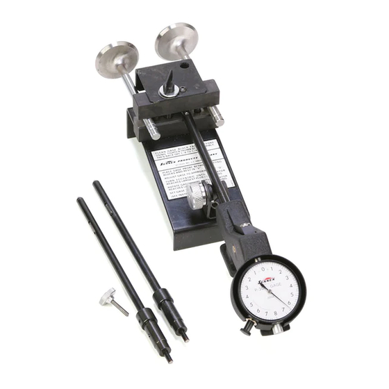
DESCRIPTION The P-310 Gage Set consists of: P-300 Gage P-312 Probe - 5/16" (7.9 mm) diameter* P-344 Probe - 11/32" (8.7 mm) diameter* P-375 Probe - 3/8" (9.5 mm) diameter* P-610 Setting Fixture P-650 Metal Storage Case - stores all items listed above;... -
Page 4: Gaging Probes
.394 to .434 10,01 to 11,02 P-438 Probe (7/16") .426 to .466 10,82 to 11,84 P-469 Probe (15/32") .457 to .497 11,61 to 12,62 P-500 Probe (1 /2") .488 to .528 12,40 to 13,41 *Included with P-310 Valve Guide Gage Set... -
Page 5: Operation
OPERATION ASSEMBLING PROBE TO GAGE 1. Select correct probe. 2. Use Wrench to back out Probe Locking Screw. 3. Install head of probe into Gage Body with flat toward Retracting Lever and countersink toward T-Handle. 4. Hold probe tightly into Gage Body and tighten Probe Locking Screw with Wrench (see Figure 3). -
Page 6: Setting Gage To Read Valve Size
FIGURE 5 tighter Thumb Screw with fingers, then back off Thumb Screw 1/8 to 1/4 turn to eliminate possibility of distortion in Blocks. CAUTION Do not use pliers or wrench. 3. Turn Eccentric until "V" is in lowest posi-tion. Setting fixture is now ready to use. -
Page 7: Using The Gage
FIGURE 6 6. Carefully remove Wrench without disturbing gage setting and store in setting fixture. 7. Recheck gage setting by rotating Probe. NOTE: Do not move dial face. Fine adjust ments should be made with Wrench. 8. Gage is now set to valve size, and is ready to use in checking condition of guides. - Page 8 NOTE: Guide can be gaged from either side of head. For accurate gaging, do not let Gaging Points extend beyond either end of valve guide bore. If Probe should come out of bore, press Retracting Lever and reposition Points inside guide bore. 3.
-
Page 9: Maintenance
MAINTENANCE MAINTENANCE OF PROBE If gaging action becomes sluggish or if gaging points stick open, probe may be disassembled for cleaning (see Figure 7). 1. Loosen Set Screw with 5/64" (2 mm) Hex Key Wrench and remove Head. 2. Remove Wedge from Tube carefully. Do not lose Spring. 3. - Page 10 ANVIL SPRING SOCKETS FIGURE 9 3. With Shaft removed, Lever may be lifted out of body for servicing. CAUTION A small Spring is used to provide gaging, force. This Spring is nested in two Sockets (one in the Lever and one in the body). Do not lose this Spring or gage will be inoperative (see Figure 9).
- Page 11 NOTES...
- Page 12 “SUNNEN AND THE SUNNEN LOGO ARE REGISTERED TRADEMARKS OF SUNNEN PRODUCTS COMPANY.” SUNNEN PRODUCTS LIMITED Sunnen ® reserves the right to change or No. 1 Centro, Maxted Road revise specifications and product design Hemel Hempstead, Herts HP2 7EF ENGLAND in connection with any feature of our...
Need help?
Do you have a question about the P-310 and is the answer not in the manual?
Questions and answers