Table of Contents
Advertisement
USER MANUAL
AFTER SALES SUPPORT:
WWW.SPTOOLS.COM
IMPORTANT
ALL PERSONS WHO ARE TO USE THIS EQUIPMENT MUST THOROUGHLY READ
AND UNDERSTAND THIS INSTRUCTION MANUAL PRIOR TO OPERATION.
SP62012
DIGITAL
MULTIMETER
ELECTRICAL
RETAIN THESE INSTRUCTIONS
AND ATTACH RECEIPT TO
MANUAL FOR FUTURE
NOTE: Proof of purchase must be retained by
the customer as it will be required in the
event of a claim under warranty.
AUSTRALIA: Visit the website's contact page to get in
touch with your local service department.
INTERNATIONAL: Use the county selector to get in touch
with your service department in your country or region.
REFERENCE
Advertisement
Table of Contents

Related Manuals for SP tools SP62012

Summary of Contents for SP tools SP62012
- Page 1 USER MANUAL SP62012 DIGITAL MULTIMETER ELECTRICAL RETAIN THESE INSTRUCTIONS AND ATTACH RECEIPT TO MANUAL FOR FUTURE REFERENCE NOTE: Proof of purchase must be retained by the customer as it will be required in the event of a claim under warranty.
-
Page 2: Table Of Contents
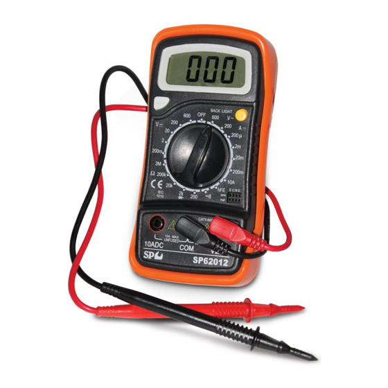
The meter is a handheld 31/2 digital Multimeter for measuring DC and AC voltage, DC current, Resistance, Diode, Transistor and Continuity Test with battery operated systems. Scope of Delivery • 1 x SP62012 Multimeter, 1 x Black Test Lead, 1 x Red Test Lead & 1 x 9V Battery... -
Page 3: Technical Specifications
Technical Specifications Maximum voltage between CAT II 600v terminals and earth ground Fuse protection F 200mA/250V Power supply 9V battery Display LCD, 1999 counts, updates 2-3/ sec Measuring method Dual-Slope Integration A/D converter Over range indication Only figure “1” on the display Polarity indication ‘’-‘’... -
Page 4: Features
Features 1. Display 3 ½ digit, 7 segments, 15mm high LCD 2. Back Light (option) When this button is pushed, the Back Light of the display is on. After about 5 seconds, the Back Light has an auto off function. Just push the button once to turn on again. -
Page 5: Intended Use
Intended Use • Never exceed the protection limit values indicated in the specifications for each range of measurement. • When the meter is linked to a measurement circuit, do not touch unused terminals. • Never use the meter to measure voltages that might exceed 600v above earth ground in category II installations. -
Page 6: Safety Information
Safety Information This multimeter has been designed according to IEC-1010 concerning electronic measuring instruments with an over voltage category (CAT II) and pollution 2. Follow all safety and operating instructions to ensure that the meter is used safely and is kept in a good condition. Full compliance with safety standards can be guaranteed only with test leads supplied. -
Page 7: Operating Instructions Dc Voltage
OPERATING INSTRUCTIONS DC Voltage Range Resolution Accuracy 200mV 100µV ±0.5% of rdg ± 2 digits ±0.5% of rdg ± 2 digits 10mV ±0.5% of rdg ± 2 digits 200V 100mV ±0.5% of rdg ± 2 digits 600V ±0.8% of rdg ± 2 digits Overload Protection: 250V rms. -
Page 8: Ac Voltage
AC Voltage Range Resolution Accuracy 200V 100mV ±1.2 % of rdg ± 10 digits 600V ±1.2 % of rdg ± 10 digits Overload Protection: 600V dc or rms. Ac for all ranges. Frequency range: 40Hz to 400Hz. Response: Average responding, calibrated in rms of a sine wave Diode &... -
Page 9: Resistance
Resistance Range Resolution Accuracy 200Ω 0.1Ω ±0.8% of rdg ± 3 digits 2kΩ 1Ω ±0.8% of rdg ± 2 digits 20kΩ 10Ω ±0.8% of rdg ± 2 digits 200kΩ 100Ω ±0.8% of rdg ± 2 digits 2MΩ 1kΩ ±1.0% of rdg ± 2 digits Maximum Open Circuit Voltage: 3.2V Overload Protection: 250V dc or rms. -
Page 10: Dc Current Measurement
DC Current Measurement 1. For measurements between 200mA and 10A, put the red test lead in the 10A jack 2. Set the rotary switch at the desired DCA position. 3. Open the circuit in which the current is to be measured, and connect the test leads in series with the circuit. -
Page 11: Transistor Test
Transistor Test 1. Set the rotary switch to the ‘’hFE’’ position. 2. Determine whether the transistor under testing is NPN or PNP and locate the emitter, base and collector leads. Insert then leads into the proper holes of the hFE socket on the front of the panel. 3. -
Page 12: Cleaning And Maintenance
Cleaning & Maintenance • Before opening the case, always disconnect test leads from all energized circuits • For protection against fire, replace fuse only with the specified voltage and current ratings (F 200mA/250V quick acting) • Never use the meter unless the back cover is in place and fastened completely. -
Page 13: Warranty Details
To the extent permitted by law and subject to this Limited Warranty, and as part of the terms of the sale of the equipment or part thereof: SP Tools shall not be liable for any form of loss, damage, cost, injury or harm of any kind (whether direct, indirect, special or consequential) howsoever arising from the use or supply of the equipment to the purchaser.
Need help?
Do you have a question about the SP62012 and is the answer not in the manual?
Questions and answers