Table of Contents
Advertisement
Quick Links
CARE INSTRUCTIONS:
WIPE CLEAN WITH SOFT DAMP CLOTH. DO NOT USE SCOURERS, ABRASIVES OR CHEMICAL SOLVENTS. STORE IN A DRY PLACE AND KEEP AWAY FROM DIRECT WATER
AND SUNLIGHT. FOR INDOOR AND DOMESTIC USE.
WARNING:
DO NOT STAND OR SIT ON THE PRODUCT. DO NOT USE THE PRODUCT AS A STEP LADDER. DO NOT USE THE PRODUCT UNLESS ALL BOLTS AND SCREWS ARE FIRMLY
SECURED. FAILURE TO FOLLOW THESE WARNING COULD RESULT IN SERIOUS INJURY. MAXIMUM SAFE LOAD: 10KGS FOR TOP PANEL,3KGS FOR DRAWER.
10PCS
A
6X35mm
B
10PCS
15x9mm
C
12PCS
6x30mm
11PCS
D
4X35mm
E
4PCS
Glide
F
8PCS
M6X45mm
8PCS
G
Flat Washer
1
2
5
12
3
4
6
6
6
Assembly Instructions
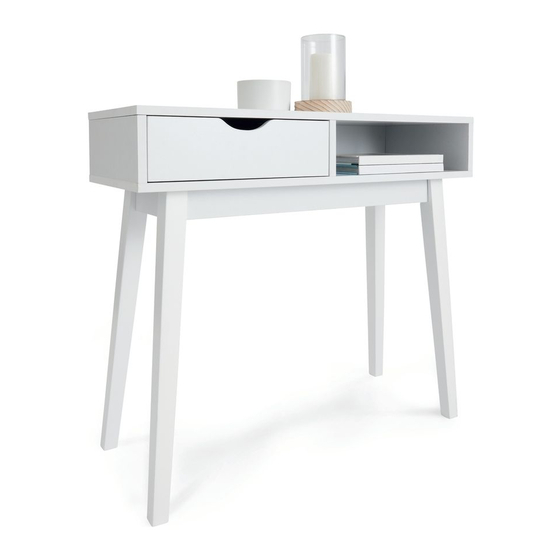
42909224 HALL TABLE WHITE
Hardware list
H
Spring Washer
I
Allen Key
J
Anti Tip Strap
K
Plastic Anchor
L
Pan Screw
M
Flat Washer
N
Paper Cover
7
10
11
9
6
8PCS
1PC
1PC
1
1PC
1PC
2PCS
2PCS
4
7
10
1PC
1PC
2
1PC
1PC
5
6
1PC
1PC
8
9
1PC
1PC
11
1PC
3
4PCS
1PC
1PC
12
Advertisement
Table of Contents

Related Manuals for KMART 42909224


Summary of Contents for KMART 42909224
- Page 1 Assembly Instructions 42909224 HALL TABLE WHITE CARE INSTRUCTIONS: WIPE CLEAN WITH SOFT DAMP CLOTH. DO NOT USE SCOURERS, ABRASIVES OR CHEMICAL SOLVENTS. STORE IN A DRY PLACE AND KEEP AWAY FROM DIRECT WATER AND SUNLIGHT. FOR INDOOR AND DOMESTIC USE.
- Page 2 STEP 1 STEP 3 Fix part A onto board 1 into the corresponding position as per diagram. Put board 5 onto board 2 & 3 into the corresponding position as per diagram. STEP 2 STEP 4 Attach board 2 & 3 &12 onto board 1 with part B & C. Put part N onto screw holes of board 2 into the corresponding position as per diagram.
- Page 3 STEP 5 STEP 7 Fix part A onto board 11 into the corresponding position as per diagram. Attach board 7 & 9 onto board 11 with part B. Attach leg 6 onto board 4 with part G,H,F & I. STEP 8 STEP 6 Attach Anti Tip Strap J onto board 4 with part L &M into the corresponding position as per diagram.
- Page 4 STEP 9 STEP 11 Finish the assembly. Predrill the hole at wall, insert part K into hole, Attach board 8 onto board 7 & 9 with part D. attach Anti Tip Strap J with part D & M into the corresponding position as per diagram.
Need help?
Do you have a question about the 42909224 and is the answer not in the manual?
Questions and answers